MS51
Nov. 28, 2019 Page 477 of 491 Rev 1.00
MS51 32K SERIES TECHNICAL REFERENCE MANUAL
default value of BODEN, BODVL and BODRSTEN (SYS_BODCTL[3]) is set by Flash controller user
configuration register CBODEN (CONFIG0 [19]), CBOV (CONFIG0 [23:21]) and
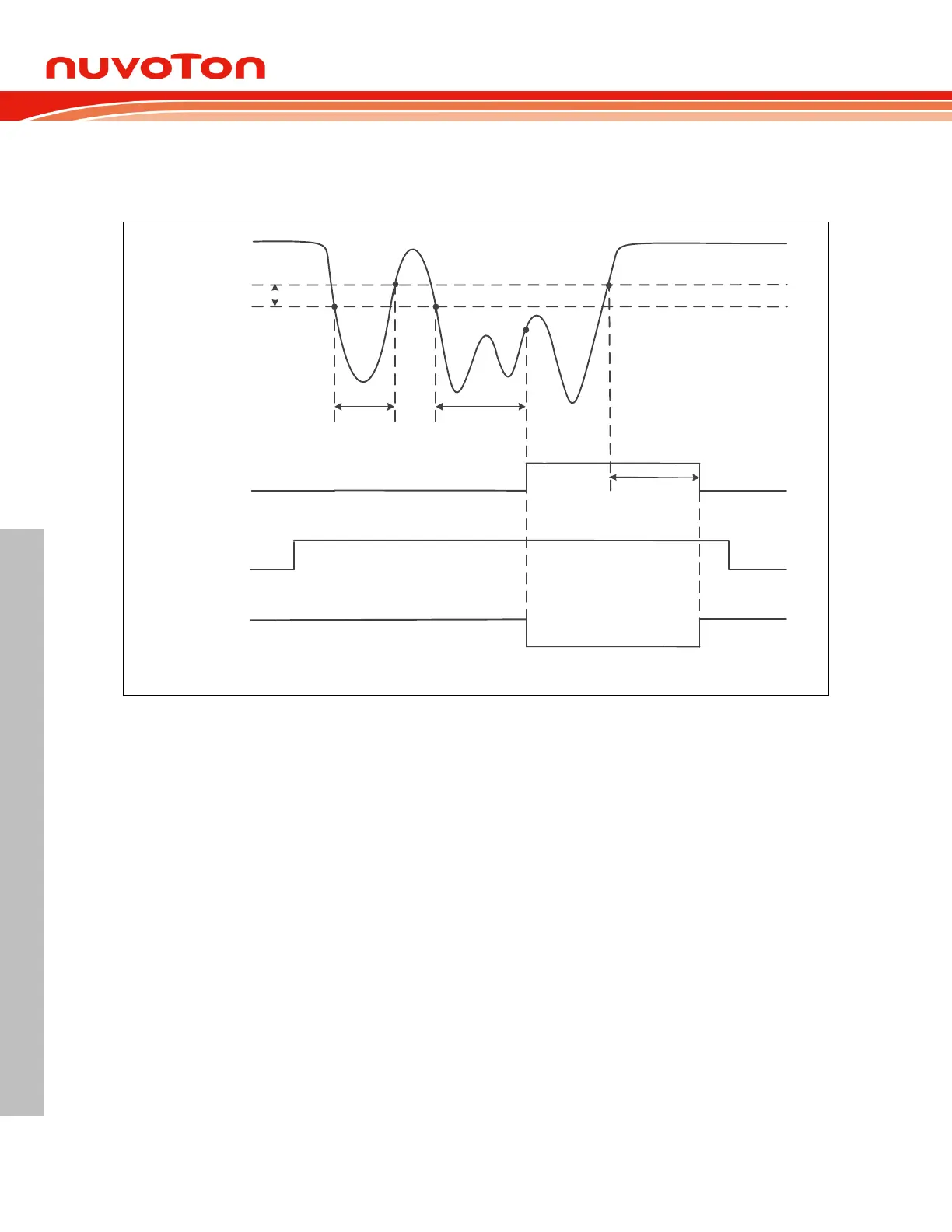
CBORST(CONFIG0[20]) respectively. User can determine the initial BOD setting by setting the
CONFIG0 register. Figure 7.3-5 shows the Brown-out Detector waveform.
AV
DD
V
BODL
BODOUT
BODRSTEN
Brown-out
Reset
T
1
(< BODDGSEL)
T
2
(= BODDGSEL)
T
3
(= BODDGSEL)
Hysteresis
V
BODH
Figure 7.3-5 Brown-out Detector (BOD) Waveform
Watchdog Timer Reset (WDT) 7.3.1.10
In most industrial applications, system reliability is very important. To automatically recover the MCU
from failure status is one way to improve system reliability. The watchdog timer(WDT) is widely used
to check if the system works fine. If the MCU is crashed or out of control, it may cause the watchdog
time-out. User may decide to enable system reset during watchdog time-out to recover the system and
take action for the system crash/out-of-control after reset.
Software can check if the reset is caused by watchdog time-out to indicate the previous reset is a
watchdog reset and handle the failure of MCU after watchdog time-out reset by checking
WDTRF(SYS_RSTSTS[2]).