MS51
Nov. 28, 2019 Page 274 of 491 Rev 1.00
MS51 32K SERIES TECHNICAL REFERENCE MANUAL
Figure 6.4-3 Input-Only Mode Structure
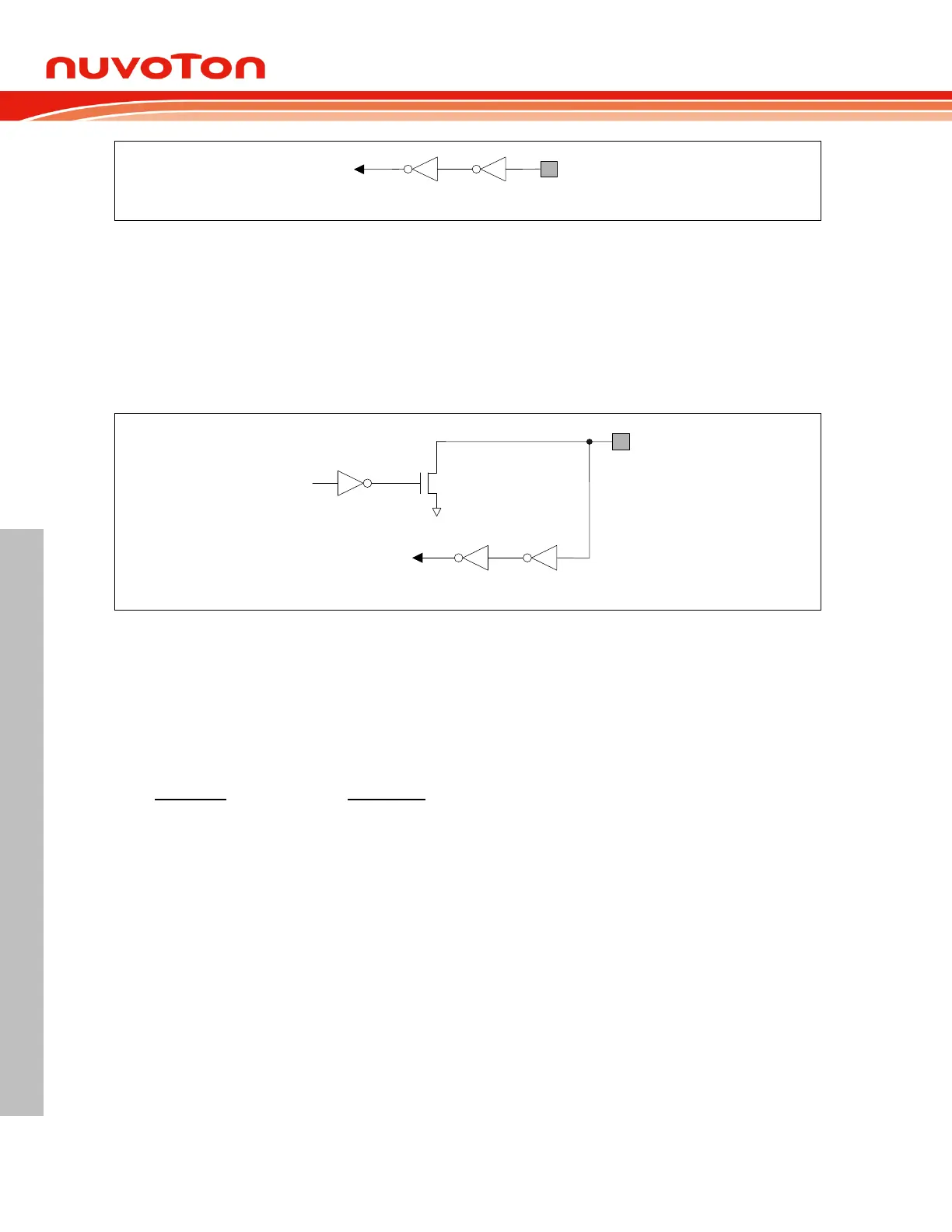
Open-Drain Mode 6.4.1.4
The open-drain mode turns off all pull-high transistors and only drives the pull-low of the port pin when
the port latch is given by logic 0. If the port latch is logic 1, it behaves as if in input-only mode. To be
used as an output pin generally as I
2
C lines, an open-drain pin should add an external pull-high,
typically a resistor tied to V
DD
. User needs to take care that an open-drain pin with its port latch as
logic 1 should be given with a determined voltage level by external devices or resistors. A floating pin
will induce leakage current especially in Power-down mode.
Figure 6.4-4 Open-Drain Mode Structure
6.4.2 Read-Modify-Write Instructions
Instructions that read a byte from SFR or internal RAM, modify it, and rewrite it back, are called “Read-
Modify-Write” instructions. When the destination is an I/O port or a port bit, these instructions read the
internal output latch rather than the external pin state. This kind of instructions read the port SFR
value, modify it and write back to the port SFR. All “Read-Modify-Write” instructions are listed as
follows.
Instruction Description
ANL Logical AND. (ANL direct, A and ANL direct, #data)
ORL Logical OR. (ORL direct, A and ORL direct, #data)
XRL Logical exclusive OR. (XRL direct, A and XRL direct, #data)
JBC Jump if bit = 1 and clear it. (JBC bit, rel)
CPL Complement bit. (CPL bit)
INC Increment. (INC direct)
DEC Decrement. (DEC direct)
DJNZ Decrement and jump if not zero. (DJNZ direct, rel)
MOV bit, C Move carry to bit. (MOV bit, C)
CLR bit Clear bit. (CLR bit)
SETB bit Set bit. (SETB bit)
The last three seem not obviously “Read-Modify-Write” instructions but actually they are. They read