MS51
Nov. 28, 2019 Page 273 of 491 Rev 1.00
MS51 32K SERIES TECHNICAL REFERENCE MANUAL
Port Pin
2-CPU-clock
delay
Input
Port Latch
P P
N
V
DD
Strong
Very
Weak
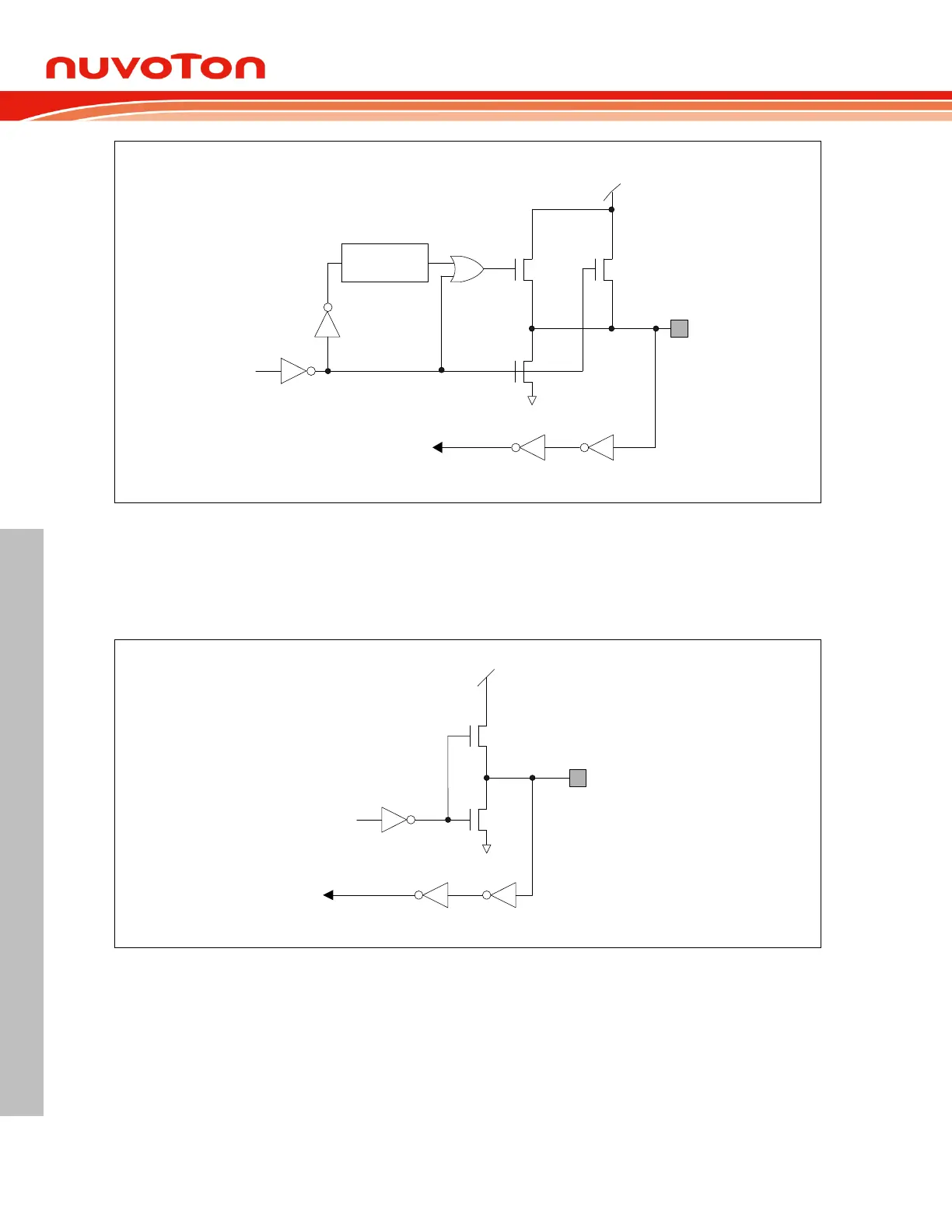
Figure 6.4-1 Quasi-Bidirectional Mode Structure
Push-Pull Mode 6.4.1.2
The push-pull mode has the same pull-low structure as the quasi-bidirectional mode, but provides a
continuous strong pull-high when the port latch is written by logic 1. The push-pull mode is generally
used as output pin when more source current is needed for an output driving.
Port Pin
Input
Port Latch
P
N
V
DD
Strong
Figure 6.4-2 Push-Pull Mode Structure
Input-Only Mode 6.4.1.3
Input-only mode provides true high-impedance input path. Although a quasi-bidirectional mode I/O can
also be an input pin, but it requires relative strong input source. Input-only mode also benefits to power
consumption reduction for logic 0 input always consumes current from V
DD
if in quasi-bidirectional
mode. User needs to take care that an input-only mode pin should be given with a determined voltage
level by external devices or resistors. A floating pin will induce leakage current especially in Power-
down mode.