MS51
Nov. 28, 2019 Page 323 of 491 Rev 1.00
MS51 32K SERIES TECHNICAL REFERENCE MANUAL
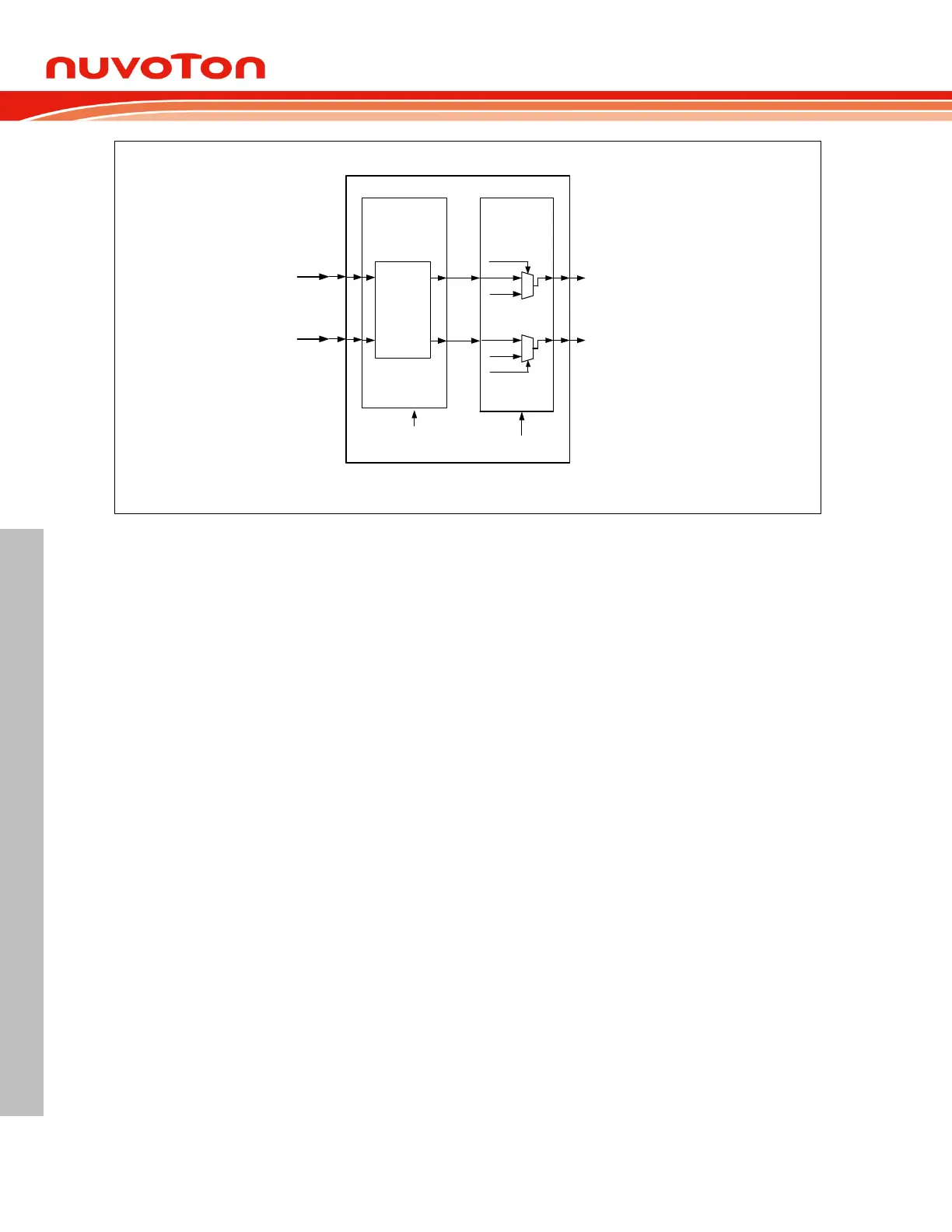
PnG0
PnG1
PWM1/2/3 output control
PWM
mode
select
PWMnMOD[1:0]
(PWMnCON1[7:6])
Mask
output
PWMnMD0
PWMnMEN0
PWMnMD1
PWMnMEN1
PWMnC0/1
mode
0
1
0
1
PWMnMEN,
PWMnMD
PWMn_CH0
PWMn_CH1
Figure 6.6-4 PWM1/2/3 Control Block Diagram
NOTE: A loading of new period and duty by setting LOAD should be ensured complete by monitoring
it and waiting for a hardware automatic clearing LOAD bit. Any updating of PWM control registers
during LOAD bit as logic 1 will cause unpredictable output.
PWM Types 6.6.2.2
The PWM generator provides two PWM types: edge-aligned or center-aligned. PWM type is selected
by PWMTYP (PWMnCON1.4).
Edge-Aligned Type 6.6.2.3
In edge-aligned mode, the 16-bit counter uses single slop operation by counting up from 0000H to
{PWMnPH, PWMnPL} and then starting from 0000H. The PWM generator signal (PnGx before PWM
and Fault Brake output control) is cleared on the compare match of 16-bit counter and the duty
register {PWMnCxH, PWMnCxL} and set at the 16-bit counter is 0000H. The result PWM output
waveform is left-edge aligned.
 Loading...


