MS51
Nov. 28, 2019 Page 272 of 491 Rev 1.00
MS51 32K SERIES TECHNICAL REFERENCE MANUAL
6.4 General Purpose I/O (GPIO)
6.4.1 Gpio Mode
The MS51 has a maximum of 30 general purpose I/O pins which 29 bit-addressable general I/O pins
grouped as 4 ports, P0 to P3, and 1 input only pin as P20. Each port has its port control register (Px
register). The writing and reading of a port control register have different meanings. A write to port
control register sets the port output latch logic value, whereas a read gets the port pin logic state.
These four modes are quasi-bidirectional (standard 8051 port structure), push-pull, input-only, and
open-drain modes. Each port spends two special function registers PxM1 and PxM2 to select the I/O
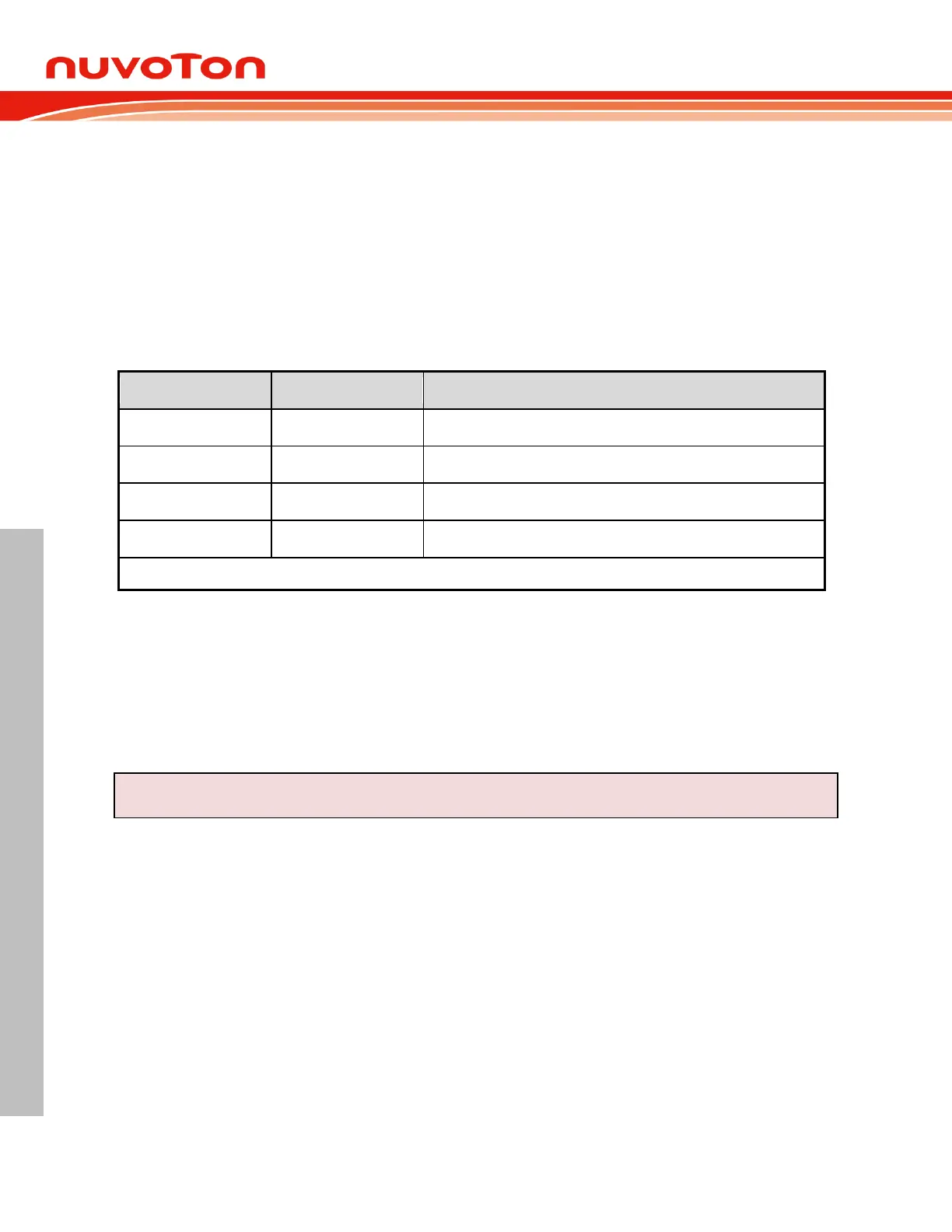
mode of port Px. The list below illustrates how to select the I/O mode of Px.n. Note that the default
configuration of is input-only (high-impedance) after any reset.
Input-only (high-impedance)
Table 6.4-1 Configuration for Different I/O Modes
All I/O pins can be selected as TTL level inputs or Schmitt triggered inputs by selecting corresponding
bit in PxS register. Schmitt triggered input has better glitch suppression capability. All I/O pins also
have bit-controllable, slew rate select ability via software. The control registers are PxSR. By default,
the slew rate is slow. If user would like to increase the I/O output speed, setting the corresponding bit
in PxSR, the slew rate is selected in a faster level.
For example:
P0M1 |= 0x40;
P0M2 &= 0xBF; //Set P0.6 as input only mode
Quasi-Bidirectional Mode 6.4.1.1
The quasi-bidirectional mode, as the standard 8051 I/O structure, can rule as both input and output.
When the port outputs a logic high, it is weakly driven, allowing an external device to pull the pin low.
When the pin is pulled low, it is driven strongly and able to sink a large current. In the quasi-
bidirectional I/O structure, there are two pull-high transistors. Each of them serves different purposes.
One of these pull-highs, called the “very weak” pull-high, is turned on whenever the port latch contains
logic 1. The “very weak” pull-high sources a very small current that will pull the pin high if it is left
floating.
The second pull-high is the “strong” pull-high. This pull-high is used to speed up 0-to-1 transitions on a
quasi-bidirectional port pin when the port latch changes from logic 0 to logic 1. When this occurs, the
strong pull-high turns on for two-CPU-clock time to pull the port pin high quickly. Then it turns off “very
weak” pull-highs continue remaining the port pin high. The quasi-bidirectional port structure is shown
below.
 Loading...


