MS51
Nov. 28, 2019 Page 288 of 491 Rev 1.00
MS51 32K SERIES TECHNICAL REFERENCE MANUAL
Figure 6.5-1 Timer/Counters 0 and 1 in Mode 0
Mode 1 (16-Bit Timer)
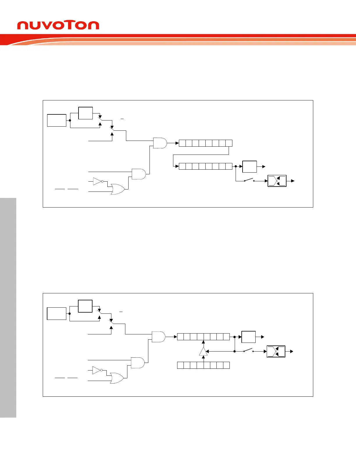
6.5.1.3
Mode 1 is similar to Mode 0 except that the counting registers are fully used as a 16-bit counter. Roll-
over occurs when a count moves FFFFH to 0000H. The Timer overflow flag TF0 (TF1) of the relevant
Timer/Counter is set and an interrupt will occurs if enabled.
TF0
(TF1)
TH0 (TH1)
TL0 (TL1)
Timer Interrupt
0 7
0 7
T0 (T1) pin
T0OE
(T1OE)
0
1
T0 (T1) pin
C/T
GATE
TR0 (TR1)
F
SYS
INT0 (INT1) pin
1/12
0
1
T0M
(T1M)
Figure 6.5-2 Timer/Counters 0 and 1 in Mode 1
Mode 2 (8-Bit Auto-Reload Timer) 6.5.1.4
In Mode 2, the Timer/Counter is in auto-reload mode. In this mode, TL0 (TL1) acts as an 8-bit count
register whereas TH0 (TH1) holds the reload value. When the TL0 (TL1) register overflow, the TF0
(TF1) bit in TCON is set and TL0 (TL1) is reloaded with the contents of TH0 (TH1) and the counting
process continues from here. The reload operation leaves the contents of the TH0 (TH1) register
unchanged. This feature is best suitable for UART baud rate generator for it runs without continuous
software intervention. Note that only Timer1 can be the baud rate source for UART. Counting is
enabled by setting the TR0 (TR1) bit as 1 and proper setting of GATE and INT0
(INT1
) pins. The
functions of GATE and INT0
(INT1
) pins are just the same as Mode 0 and 1.
TF0
(TF1)
TH0 (TH1)
TL0 (TL1)
Timer Interrupt
0 7
0 7
T0 (T1) pin
T0OE
(T1OE)
0
1
T0 (T1) pin
C/T
GATE
TR0 (TR1)
F
SYS
INT0 (INT1) pin
1/12
0
1
T0M
(T1M)
Figure 6.5-3 Timer/Counters 0 and 1 in Mode 2