MS51
Nov. 28, 2019 Page 324 of 491 Rev 1.00
MS51 32K SERIES TECHNICAL REFERENCE MANUAL
PWMnP (2nd)
PWMnP (1st)
PWMnCH01
(2nd)
PWMnCH01
(1st)
PG01 output
Load
PWMnCH01
(2nd)
Load
PWMnP (2nd)
PWMnCH01
(2nd)
duty valid
PWMnP (2nd) period
valid
12-bit counter
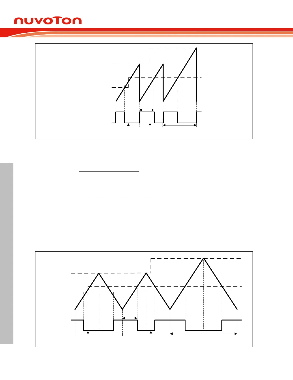
Figure 6.6-5 PWM Edge-aligned Type Waveform
The output frequency and duty cycle for edge-aligned PWM are given by following equations:
PWM frequency =
(F
PWM
is the PWM clock source frequency divided by
PWMDIV).
PWM high level duty =
1},{
},{
PWMnPLPWMnPH
PWMnCHxLPWMnCHxH
.
Center-Aligned Type 6.6.2.4
In center-aligned mode, the 16-bit counter use dual slop operation by counting up from 0000H to
{PWMnPH, PWMnPL} and then counting down from {PWMnPH, PWMnPL} to 0000H. The PnGx
signal is cleared on the up-count compare match of 16-bit counter and the duty register {PWMnCxH,
PWMnCxL} and set on the down-count compare match. Center-aligned PWM may be used to
generate non-overlapping waveforms.
PWMP (2nd)
PWMP (1st)
PWM01 (2nd)
PWM01 (1st)
PG01 output
Load
PWM01 (2nd)
Load
PWMP (2nd)
PWM01 (2nd)
duty valid
PWMP (2nd) period valid
12-bit counter
Figure 6.6-6 PWM Center-aligned Type Waveform