MS51
Nov. 28, 2019 Page 291 of 491 Rev 1.00
MS51 32K SERIES TECHNICAL REFERENCE MANUAL
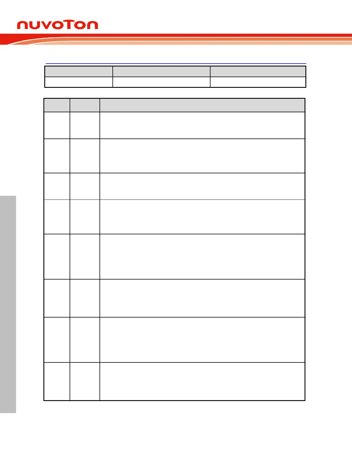
TCON – Timer 0 and 1 Control
88H, All pages, Bit-addressable
Timer 1 overflow flag
This bit is set when Timer 1 overflows. It is automatically cleared by hardware when the program
executes the Timer 1 interrupt service routine. This bit can be set or cleared by software.
Timer 1 run control
0 = Timer 1 Disabled. Clearing this bit will halt Timer 1 and the current count will be preserved in
TH1 and TL1.
1 = Timer 1 Enabled.
Timer 0 overflow flag
This bit is set when Timer 0 overflows. It is automatically cleared via hardware when the program
executes the Timer 0 interrupt service routine. This bit can be set or cleared by software.
Timer 0 run control
0 = Timer 0 Disabled. Clearing this bit will halt Timer 0 and the current count will be preserved in
TH0 and TL0.
1 = Timer 0 Enabled.
External interrupt 1 edge flag
If IT1 = 1 (falling edge trigger), this flag will be set by hardware when a falling edge is detected. It
remain set until cleared via software or cleared by hardware in the beginning of its interrupt service
routine.
If IT1 = 0 (low level trigger), this flag follows the inverse of the INT1
input signal’s logic level.
Software cannot control it.
External interrupt 1 type select
This bit selects by which type that INT1
is low level triggered.
1 = INT1
is falling edge triggered.
External interrupt 0 edge flag
If IT0 = 1 (falling edge trigger), this flag will be set by hardware when a falling edge is detected. It
remain set until cleared via software or cleared by hardware in the beginning of its interrupt service
routine.
If IT0 = 0 (low level trigger), this flag follows the inverse of the INT0
input signal’s logic level.
Software cannot control it.
External interrupt 0 type select
This bit selects by which type that INT0
is low level triggered.
1 = INT0
is falling edge triggered.
 Loading...


