MS51
Nov. 28, 2019 Page 296 of 491 Rev 1.00
MS51 32K SERIES TECHNICAL REFERENCE MANUAL
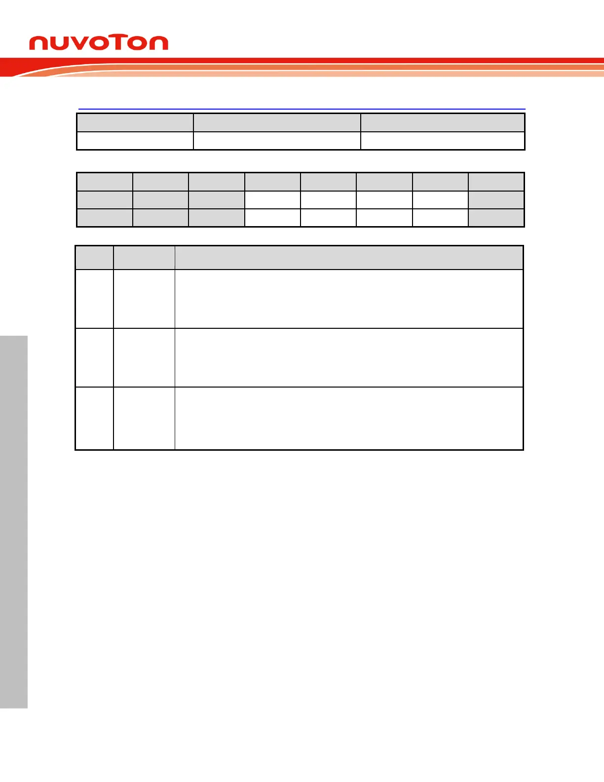
CKCON – Clock Control
Timer 1 clock mode select
0 = The clock source of Timer 1 is the system clock divided by 12. It maintains standard 8051
compatibility.
1 = The clock source of Timer 1 is direct the system clock.
Timer 0 clock mode select
0 = The clock source of Timer 0 is the system clock divided by 12. It maintains standard 8051
compatibility.
1 = The clock source of Timer 0 is direct the system clock.
Timer 0 output enable
0 = Timer 0 output Disabled.
1 = Timer 0 output Enabled from T0 pin.
Note that Timer 0 output should be enabled only when operating in its “Timer” mode.
6.5.2 Timer2 And Input Capture
Overview 6.5.2.1
Timer 2 is a 16-bit up counter cascaded with TH2, the upper 8 bits register, and TL2, the lower 8 bit
register. Equipped with RCMP2H and RCMP2L, Timer 2 can operate under compare mode and auto-
reload mode selected by CM/RL2
(T2CON.0). An 3-channel input capture module makes Timer 2
detect and measure the width or period of input pulses. The results of 3 input captures are stores in
C0H and C0L, C1H and C1L, C2H and C2L individually. The clock source of Timer 2 is from the
system clock pre-scaled by a clock divider with 8 different scales for wide field application. The clock is
enabled when TR2 (T2CON.2) is 1, and disabled when TR2 is 0. The following registers are related to
Timer 2 function.
 Loading...


