MS51
Nov. 28, 2019 Page 328 of 491 Rev 1.00
MS51 32K SERIES TECHNICAL REFERENCE MANUAL
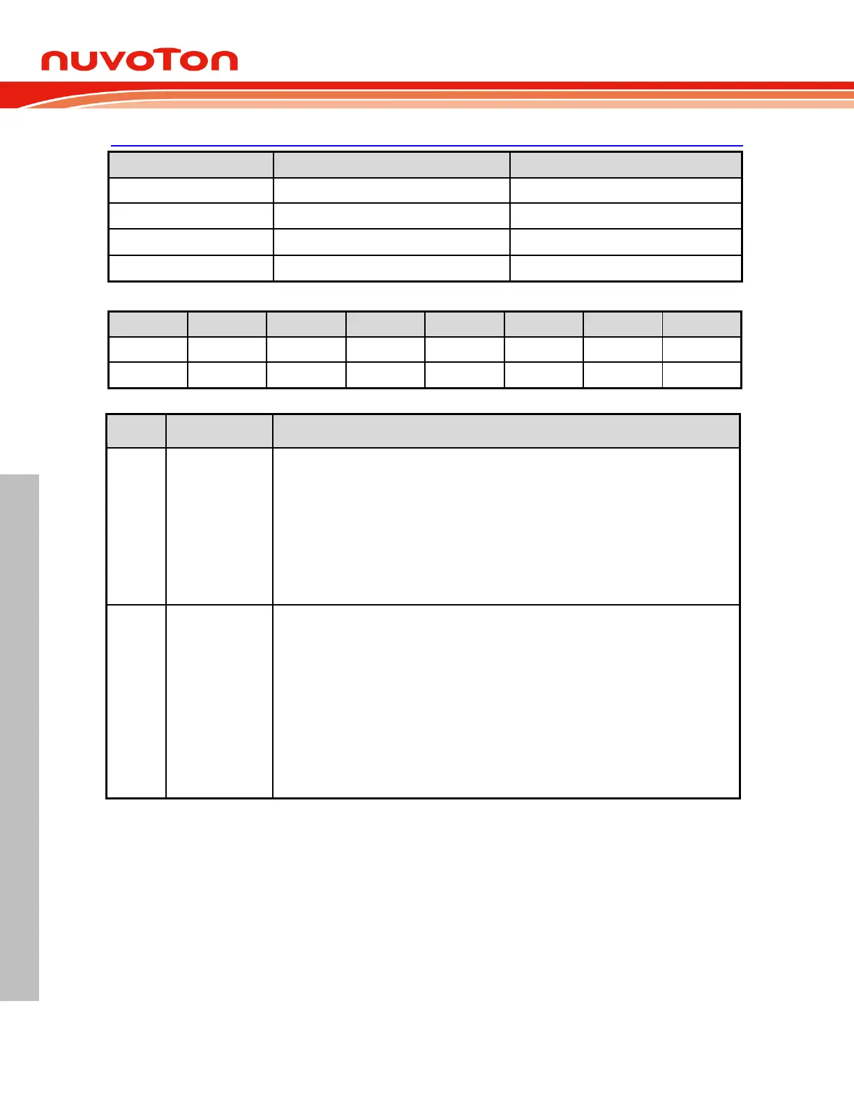
PWMnINTC – PWM Interrupt Control
PWM interrupt type select
These bit select PWM interrupt type.
00 = Falling edge on PWM channel 0/1/2/3/4/5 pin.
01 = Rising edge on PWM channel 0/1/2/3/4/5 pin.
10 = Central point of a PWM period.
11 = End point of a PWM period.
Note that the central point interrupt or the end point interrupt is only available while PWM
operates in center-aligned type.
PWM interrupt pair select
These bits select which PWM channel asserts PWM interrupt when PWM interrupt type is
selected as falling or rising edge on PWM channel 0~5 pin..
000 = PWM_CH0.
001 = PWM_CH1.
010 = PWM_CH2.
011 = PWM_CH3.
100 = PWM_CH4.
101 = PWM_CH5.
Others = PWM_CH0.
 Loading...


