MS51
Nov. 28, 2019 Page 443 of 491 Rev 1.00
MS51 32K SERIES TECHNICAL REFERENCE MANUAL
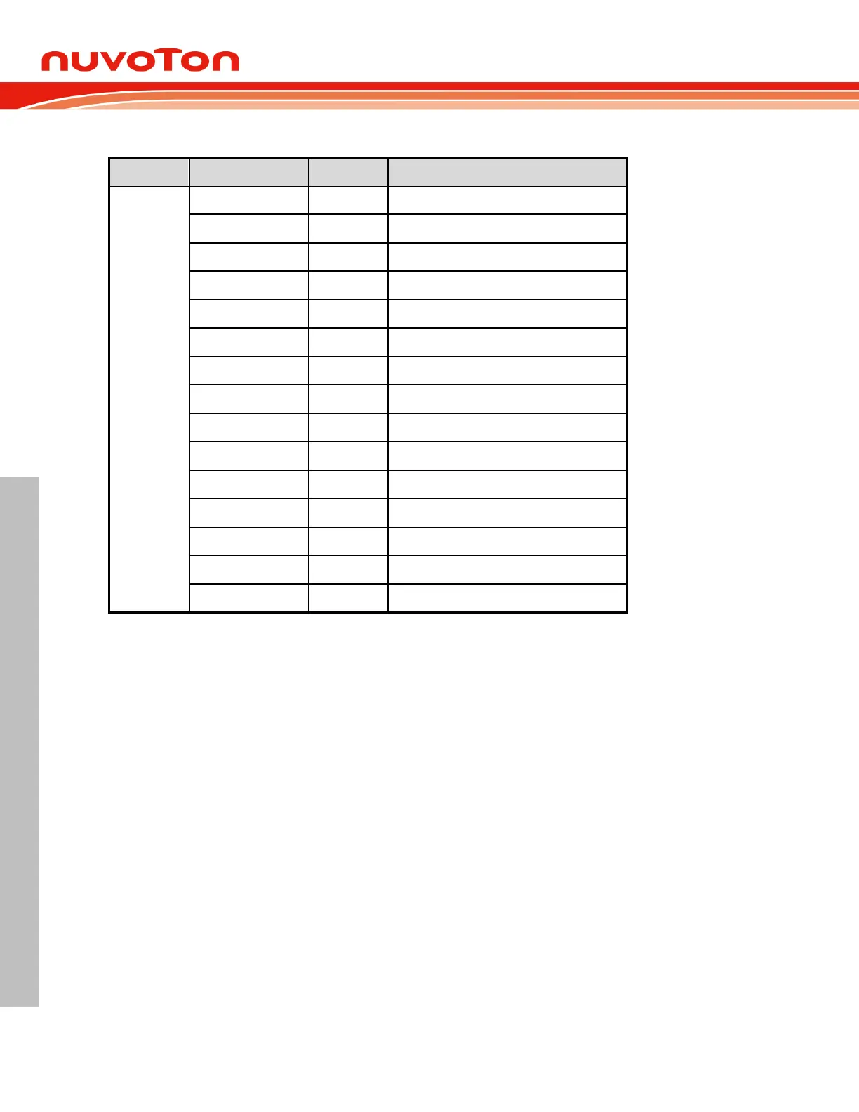
Following shows the multi function define of ADC.
ADC_ channel analog input.
ADC_ channel analog input.
ADC_ channel analog input.
ADC_ channel analog input.
ADC_ channel analog input.
ADC_ channel analog input.
ADC_ channel analog input.
ADC_ channel analog input.
ADC_ channel analog input.
ADC_ channel analog input.
ADC_ channel analog input.
ADC_ channel analog input.
ADC_ channel analog input.
ADC_ channel analog input.
ADC_ channel analog input.
ADC Conversion Triggered by External Source 6.13.2.2
Besides setting ADCS via software, the MS51 32K series is enhanced by supporting hardware
triggering method to start an A/D conversion. If ADCEX (ADCCON1.1) is set, edges or period points
on selected PWM channel or edges of STADC pin will automatically trigger an A/D conversion. (The
hardware trigger also sets ADCS by hardware.)
The effective condition is selected by ETGSEL (ADCCON0[5:4]) and ETGTYP (ADCCON1[3:2]). A
trigger delay can also be inserted between external trigger point and A/D conversion. The external
trigging ADC hardware with controllable trigger delay makes the MS51 32K series feasible for high
performance motor control. Note that during ADC is busy in converting (ADCS = 1), any conversion
triggered by software or hardware will be ignored and there is no warning presented.
 Loading...


