MS51
Nov. 28, 2019 Page 449 of 491 Rev 1.00
MS51 32K SERIES TECHNICAL REFERENCE MANUAL
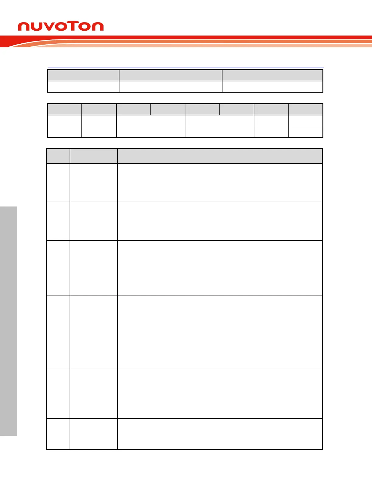
ADCCON1 – ADC Control 1
ADC Offset Calibration Enable register
This field is used to enable offset calibration function.
0: ADC Offset Calibration is enabled, auto-calibration by ADC hardware.
1: ADC Offset Calibration is disabled
External start ADC trigger pin select
0 = Assign STADC to P0.4.
1 = Assign STADC to P1.3.
Note that STADC will exchange immediately once setting or clearing this bit.
ADC ADCAQT clock divider
This field define sampoing acquisition time clock divider value
00 = F
ADCAQT
= F
SYS
/1.
01 = F
ADCAQT
= F
SYS
/2.
10 = F
ADCAQT
= F
SYS
/4.
11 = F
ADCAQT
= F
SYS
/8.
External trigger type select
When ADCEX (ADCCON1.1) is set, these bits select which condition triggers ADC
conversion.
00 = Falling edge on PWM0/2/4 or STADC pin.
01 = Rising edge on PWM0/2/4 or STADC pin.
10 = Central point of a PWM period.
11 = End point of a PWM period.
Note that the central point interrupt or the period point interrupt is only available for PWM
center-aligned type.
ADC external conversion trigger select
This bit select the methods of triggering an A/D conversion.
0 = A/D conversion is started only via setting ADCS bit.
1 = A/D conversion is started via setting ADCS bit or by external trigger source depending on
ETGSEL[1:0] and ETGTYP[1:0]. Note that while ADCS is 1 (busy in converting), the ADC will
ignore the following external trigger until ADCS is hardware cleared.
ADC enable
0 = ADC circuit off.
1 = ADC circuit on.