DMTA-20015-01EN [U8778402], Rev. M, February 2017
Connector References
71
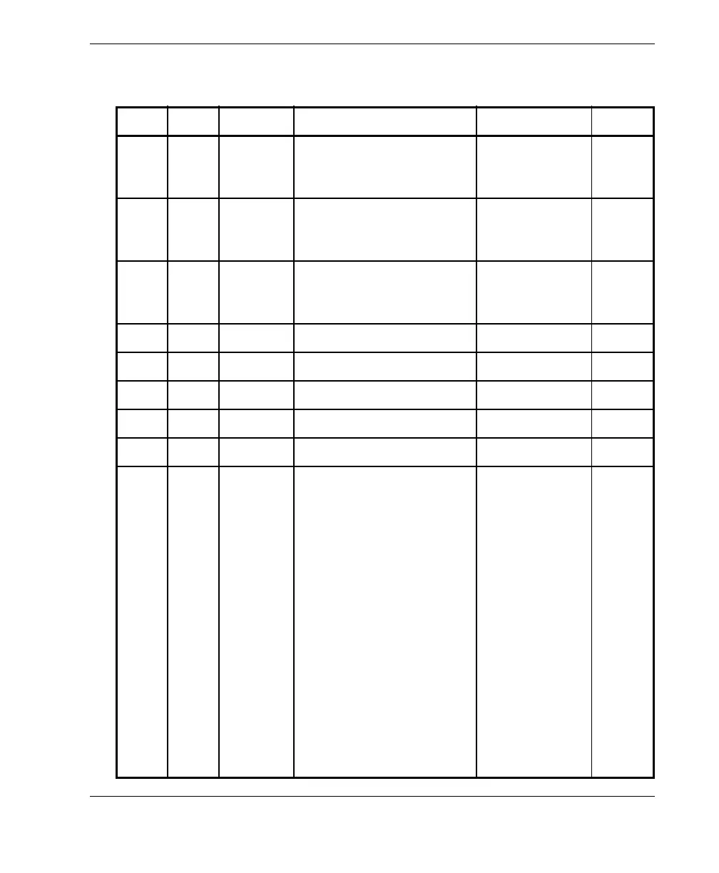
Table 14 Pinout for the alarm and I/O connector
Pin I/O Signal Description Current Level
1 Out Al1 Alarm output 1. Disabled
on reset, and is at 0 V.
When active, it is at 5 V.
±15 mA TTL
2 Out Al2 Alarm output 2. Disabled
on reset, and is at 0 V.
When active, it is at 5 V.
±15 mA TTL
3 Out Al3 Alarm output 3. Disabled
on reset, and is at 0 V.
When active, it is at 5 V.
±15 mA TTL
4 Out AOUT1 Analog output 1 ±10 mA ±5 V
5 Out AOUT2 Analog output 2 ±10 mA ±5 V
6–GNDGround N/A N/A
7 Out DOUT4 Digital output 4 ±15 mA TTL
8 Out DOUT3 Digital output 3 ±15 mA TTL
9InDIN4/
ExtPace
Digital input 4/external
pace input
Programmable input. Can
be configured as generic
input 4, or as an external
pace input (high level
with a minimum signal
length of 50 ms when
used as DIN4, or 21 µs as
ExtPace).
Refer to the
OmniScan MXU Software
User’s Manual
(“Configuring the Digital
Input”) for more
information on
programming this input.
N/A TTL