DMTA-20015-01EN [U8778402], Rev. M, February 2017
Overview of the Equipment
87
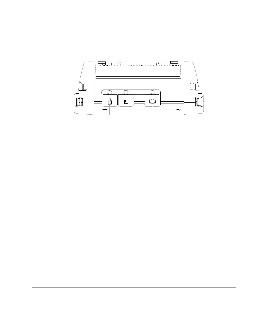
7.4 Top Panel
There are three connectors located on the top panel of the OmniScan MX (see
Figure 7-5 on page 87).
Figure 7-5 Top panel of the OmniScan MX
Scanner interface
Used to connect a mechanical scanner.
Alarm and I/O
Used as an alarm output and control input.
SVGA output
An external VGA or SVGA monitor that mirrors the OmniScan MX display may
be connected to this DB-15 port.
7.5 Rear Panel
The rear panel consists of the acquisition module currently connected to the
OmniScan MX. More information about each module’s capabilities is available in the
respective appendix.
Scanner
interface
SVGA
output
Alarm and I/O