M - 8
Example 3: For 3 bytes data registers: as shown on the Figure 8.1 as 3
rd
data string of
the Command sent section:
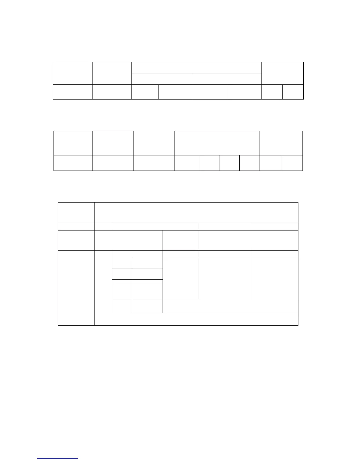
01 03 0001 0001 D5CA: is to read Setpoint 1 value (SP1).
DATA
DEVICE
ADDRESS
FUNCTION
CODE
03 or 04
STARTING REGISTER NUMBER OF REGISTERS
CRC
01 03 00 01 00 01 D5 CA
01 03 04 0010 0064 FA1D: 3
rd
Command Response on Figure 8.1 which device
responded to the 3
rd
read command.
DEVICE
ADDRESS
FUNCTION
CODE
NUMBER
OF BYTES
VALUES OF REGISTERS
(3 Bytes)
CRC
01 03 04
00
(N/A)
10 00 64
FA 1D
NOTE: SetPoints, In/Output Offset and process values (Main, Peak and Valley
Reading Values) must be determined in following manner: (using above example)
Value
Format
VALUES OF REGISTERS
(3 Hex. Bytes)
Hex. 00
10 00 64
Binary bits
pattern
N/A
XXXX
(binary bits)
XXXX
(binary
bits)
XXXX XXXX
(binary bits)
XXXX XXXX
(binary bits)
Binary N/A
0001 0000 0000 0000 0110 0100
X XXX
0 001
SIGN
DECIMAL
POINT
Absolute
Value
Absolute Value Absolute Value
Setpoints,
In/Output
Offset,
Main/ Peak/
Valley
Readings
N/A
+
FFFF. 100 (decimal)
Equivalent
Decimal
+100.
Table 8.1 Format of 3 bytes Data Value Description of SetPoints,
In/Output Offset and process values.
For detail description of How to determine Sign (+ or -) and Decimal Point Position,
refer to Section 10.28 and Table 10.16 of Communication Manual.

 Loading...


