CPC 100 V 3.20
Current Transformer - 4
Current
Transformer
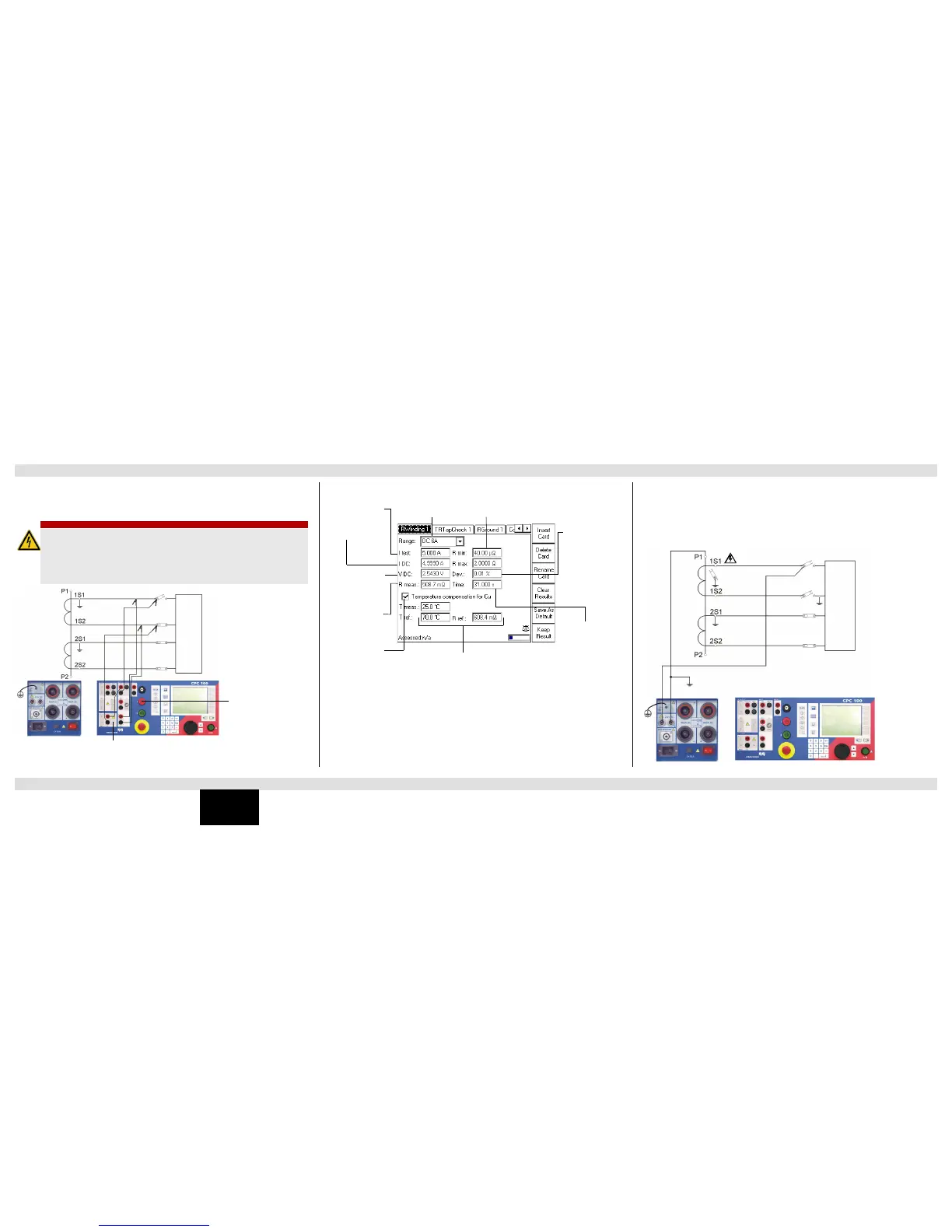
Use the test card RWinding to measure the resistance of a current transformer’s secondary
winding.
Note: If n/a appears in the VDC or Rmeas box, the VDC input is overloaded.
Use the test card VWithstand to measure the voltage withstand capability of the secondary
winding and secondary wiring. To do so, disconnect the burden. As shown in the following
figure, connect one cable of the 2kV output to the transformer’s secondary (1S1) winding
connection and the other cable to earth and the transformer’s primary connection (P1). Open
the secondary ground connection and ground the burden for safety reasons.
DANGER
Death or severe injury caused by high voltage or current
► Never open the measuring circuit while current flows.
► Check whether the red warning light “I” and the discharge LED are off before
disconnecting the device under test.
► Before disconnecting from the CPC 100, connect the device under test on both
ends to protective earth.
Output range
Actual test current
Transformer’s
winding
resistance
Enable/disable
temperature
compensation for
the result
Measured voltage
at input VDC
T meas: Actual ambient temperature
T ref: Temperature for which the result is calculated
R ref: Calculated resistance.
In Centigrade:
Rref = (V DC / I DC) x (235 °C + T ref) / (235 °C + T meas)
In Fahrenheit:
Rref = (VDC / IDC) x (391°F + Tref
F
) / (391°F + Tmeas
F
)
Formula according to IEC 60076-1
Measurement range
Total elapsed time
Maximum deviation
between the
measured values
within the last 10 s
of the
measurement. The
results are
considered stable if
Dev < 0.1 %.
Nominal test
current

 Loading...


