CP SB1
CP SB1 - 2
CP SB1
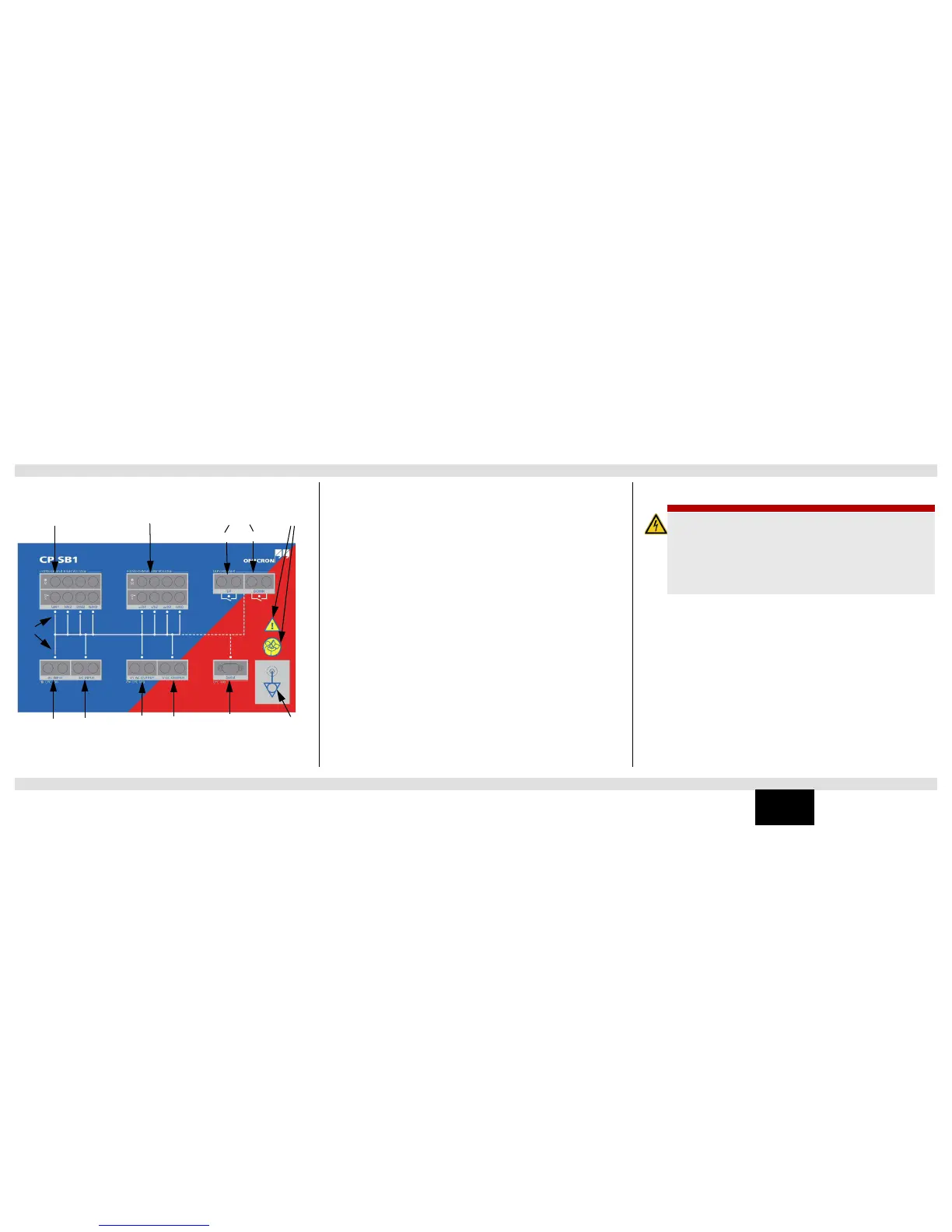
The front panel of the CP SB1 provides the following functional components:
• Transformer High Voltage:
– Outputs (Source) for the injection of current or voltage on the individual phases of the
transformer
– Inputs (Measure) for the voltage measurement
Note: The inputs and outputs of the respective connections (U/H1, V/H2, W/H3, N/H0) are
connected to the transformer using Kelvin clamps.
• Transformer Low Voltage:
– Outputs (Source) for the injection of current or voltage on the individual phases of the
transformer
– Inputs (Measure) for the voltage measurement
Note: The inputs and outputs of the respective connections (u/X1, v/x2, w/x3, n/X0) are
connected to the transformer using Kelvin clamps.
• Tap Changer: Two potential-free contacts for switching the tap changer
• AC input for connection to the 2KV AC output of the CPC 100
• DC input for connection to the 6A DC output and I AC/DC input of the CPC 100
• AC output for connection to the V1 AC input of the CPC 100
• DC output for connection to the VDC input of the CPC 100
• Serial interface for the CPC 100 (TRRatio and TRTapCheck test cards) to control the
CP SB1
• Equipotential ground terminal for grounding the CP SB1 close to the position of the
operating staff
► Switch off the power supply of the tap changer.
► Connect the Kelvin clamps to the bushings.
► Connect the cables to the Kelvin clamps. Make sure that the cables show upwards and that
each color is connected to a different phase.
► Connect the cables from the Kelvin clamps’ voltage sense outputs to the CP SB1’s
transformer inputs. Observe the color code.
► Make sure to measure the voltage to ground at the terminals of the tap changer. If no voltage
is measured, connect the flexible terminal adapters to the "up" and "down" terminals of the
tap changer.
► Connect the cables ("up", "down") to the CP SB1.
► Connect the CP SB1 to the CPC 100 according to ”Functional Components of the CP SB1”
on page CP SB1-2.
► Switch on the power supply of the tap changer.
► Remove all grounding connections of the terminals except one per winding. Use Neutral (N)
for the grounding connection if accessible.
► Start the measurement according to page Transformer-1 and page Transformer-7.
DANGER
Death or severe injury caused by high voltage or current
► Position the CP SB1 in the safety area and do not enter this area during the entire
measurement.
► Connect the CPC 100 and CP SB1 using the delivered grounding cable.
► Connect the grounding cable of the CP SB1 at a safe grounding point at the
transformer.
► Do not operate the test equipment without safe connection to ground.
► Make sure that all high-voltage connections of the transformer are removed.
► Make sure that all terminals of the transformer are connected to ground.
Functional Components of the CP SB1 Connecting the CPC 100 and CP SB1 to Power Transformers

 Loading...


