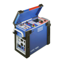
CPC 100 V 3.20
Preface - 3
► All AC and DC output sockets of the CPC 100 can carry life-hazardous voltage potential and
provide life-hazardous currents. Therefore:
► While connecting cables to the CPC 100 high-voltage or current outputs, or other
conducting parts that are not protected against accidental contact, press the Emergency
Stop button, and keep it pressed as long as an output signal is not absolutely necessary
for the test.
► When connecting to the front panel input/ output sockets, use wires with either 4 mm
safety “banana” connectors and plastic housing or, where applicable, with the especially
manufactured counterpart supplied by OMICRON electronics (e.g., for the V2 AC
measuring input).
► For the high-voltage and current output connectors on the left-hand side of the test set
(2kV AC, 400A DC and 800A AC, Ext. Booster), only use the specially manufactured
cables supplied by OMICRON electronics (refer to the chapter “Accessories” of the
CPC 100 Reference Manual available in PDF format on the CPC 100 Toolset CD-ROM
or the CPC 100 Start Page).
► One end of the high-voltage cable has a coaxial safety plug that is certified for a voltage
level of 2kV AC. The other end is equipped with a safety banana plug that is insulated
with a shrink tube. When the CPC 100 is switched on, consider this part of the cable a
hazard of electric shock.
► If you do not use the high-current outputs 400A DC or 800 A AC, or the high-voltage
output 2kV AC, disconnect any cable that may be plugged in to these sockets.
Note: The 400A DC or 800 A AC outputs are not switched off by internal relays. Therefore,
if a test mode is selected that does not use either one of these two outputs, they still
generate current.
► Do not stand right next to or directly underneath a connection point because the clamps may
fall off and touch you.
► The red warning light on the CPC 100 front panel indicates hazardous voltage and/ or
current levels at the CPC 100 outputs (red light “I” on or flashing). The green warning
light indicates that the CPC 100 outputs are not activated.
Note: If none or both warning lights are on, the unit is defective. Do not use it anymore.
► Both of the high-current output sockets on the left-hand side of the test set (400A DC
and 800 A AC) usually carry a relatively low-voltage potential. However, in case of an
internal insulation fault these outputs may carry up to 300 V. Consider these outputs life-
hazardous.
► Always lock connectors properly.
► The high-current cables for both the 800A AC and 400A DC outputs are equipped with
connection clamps at one end. If these connection clamps are attached to a test object’s
terminal that is situated above your head, make sure the clamp is securely attached. Due to
the weight of the cables the clamp may become loose and fall down.
► Do not operate the CPC 100 under ambient conditions that exceed the temperature and
humidity limits listed in ”General” on page Technical Data-3.
► Do not operate the CPC 100 in the presence of explosives, gas or vapors.
► If the CPC 100 or any add-on device or accessory does not seem to function properly, do
not use it anymore. If in doubt, call the OMICRON electronics hotline (refer to cover page of
this User Manual.
Power Supply
► Supply the CPC 100 only from a power outlet that has protective earth (PE).
► An error message (313) appears if either the PE connection is defective or the power supply
has no galvanic connection to ground. In this case, make sure that the PE connection is
intact. If the PE connection is intact and the error message still appears, select the Disable
ground check check box at the Device Setup tab in the Options view.
► Ground the isolating transformer outputs or generators used to supply the CPC 100 on the
N (neutral) output or select the Disable ground check check box as described above.
► Instead of supplying the CPC 100 from phase - neutral (L1-N, A-N), it may also be supplied
from phase - phase (e.g., L1-L2; A-B). However, the voltage must not exceed 240 V AC.
► Fuse-protect the power supply (16A slow-acting fuse).
► Do not use an extension cable on a cable reel to prevent an overheating of the cord; run out
the extension cord.
► The connector “Ext. Booster” is always galvanically connected to mains, regardless of
whether an external booster is selected on the software tab Options | Device Setup, the
green warning light (0) is on, the outputs are turned off or the Emergency Stop button is
pressed. Handle with extreme caution. Do not use any booster cables other than those
supplied by OMICRON electronics.

 Loading...