CPC 100 V 3.20
Resistance - 3
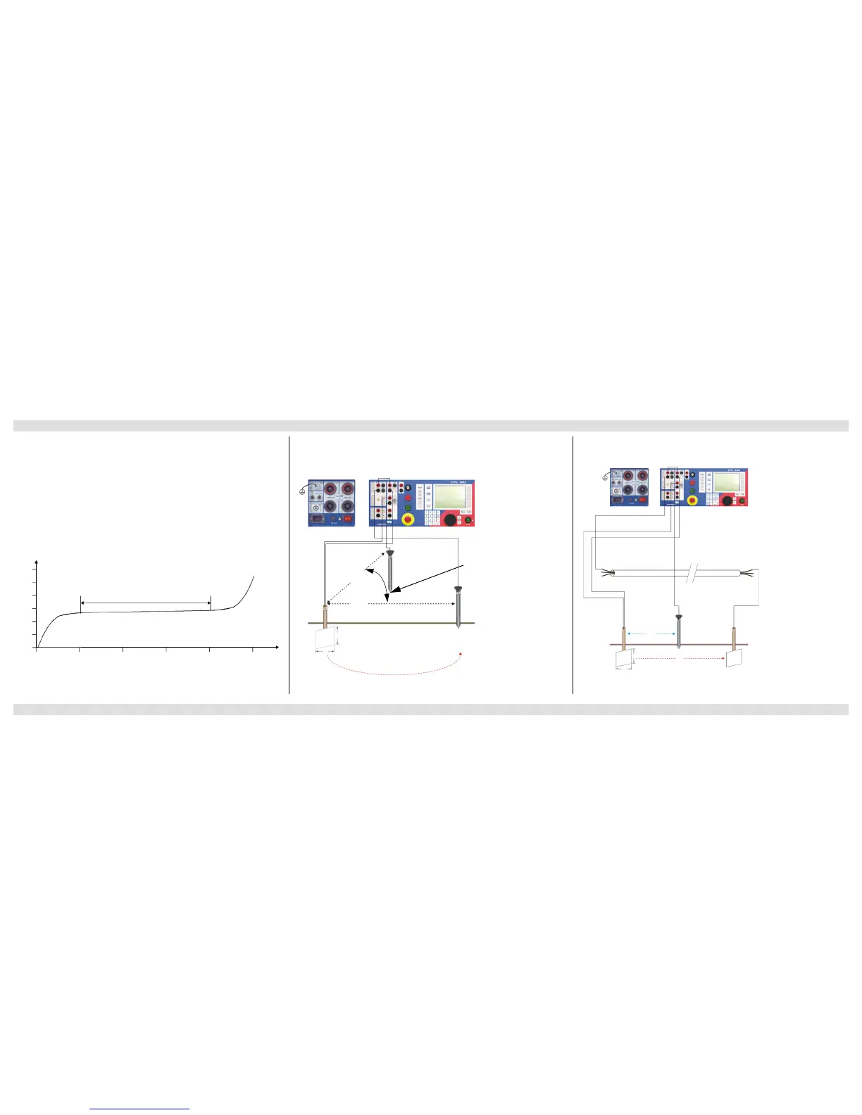
Use the RGround test card to determine earth resistance between a substation’s ground
system and a remote auxiliary electrode. To measure the earth resistance, the CPC 100 injects
AC current between the substation’s ground system and a temporary remote auxiliary electrode.
A second auxiliary electrode is used to measure the voltage potential across the substation’s
earth resistance.
Note: Make sure not to position the auxiliary electrode U too close to the substation’s ground
system. If you do so, you measure in a range where the earth resistance may not be linear (see
figure below).
We suggest to test several points using a longer distance to the substation ground. That way
you get a better understanding of where the linear range of the earth resistance lies, and where
the measurements are reliable.
Theoretical resistance characteristic of an earth electrode:
Measuring the Ground Resistance of Small Ground Systems Measuring the Ground Resistance of Large Ground Systems

 Loading...


