CPC 100 V 3.20
Introduction - 2
Introduction
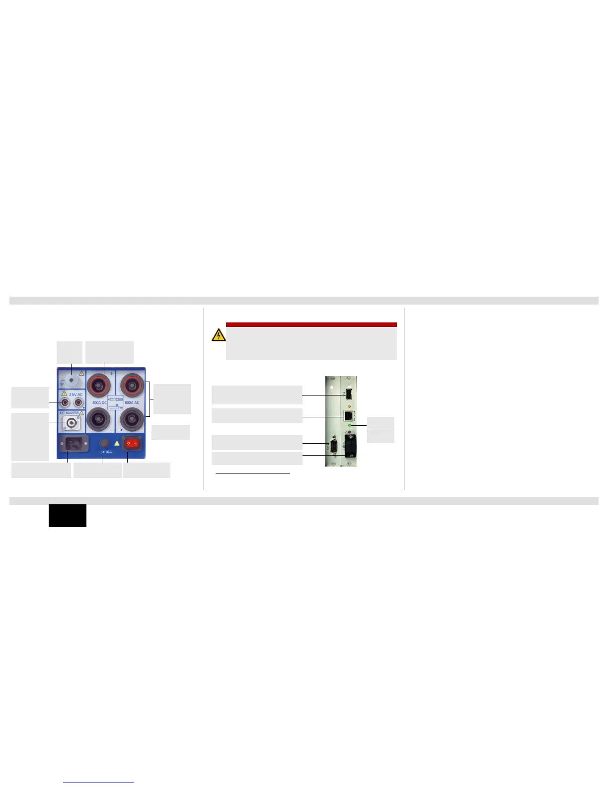
High-Voltage and Current Outputs
When the CPC 100 outputs high current, observe the allowed duty cycles that may apply to the
selected AC output range.
ePC Interfaces
1
1. For detailed information on the RJ45 connectors, see chapter “CPC 100 in a Network” in the
CPC 100 Reference Manual available in PDF format on the CPC 100 Toolsets or CPC 100
Start Page.
2. For the pin assignment of the RS232 serial interface plug, refer to the CPC 100 Reference
Manual, section “ePC Interfaces” of chapter “Technical Data”.
3. The connector for external safety functions allows connecting:
• an external Emergency Stop button
• an external “test start/ stop” push-button
• external I /O warning lights
• CP CR500
The attached plug contains a jumper for the emergency stop or “dead man” function, and as long
as the plug is placed on the connector, these functions are bridged. If the plug is removed,
emergency stop is active.
For the plug’s pin assignment and a wiring scheme, refer to section “Connector for External
Safety Functions” of chapter “Technical Data” in the CPC 100 Reference Manual available in
PDF format on the CPC 100 Toolsets or CPC 100 Start Page.
DANGER
Death or severe injury caused by high voltage or current
The connector “Ext. Booster” is always galvanically connected to mains.
► Do not use any accessories other than those supplied by OMICRON electronics.
► Do not use booster cables that are frayed or damaged in any way.
► Handle with extreme caution.
1. Older CPC 100 versions have slightly different ePC interfaces. For detailed information refer to
the CPC 100 Reference Manual.
USB connector for connecting OMICRON
electronics USB memory sticks
RJ45 socket for connecting CPC 100 to a PC
or a network hub
Serial interface connector for connecting
optional CP TD1 test set
Connector for external safety functions (see
item 3 below)
Red LED
Green LED

 Loading...


