CPC 100 V 3.20
Resistance - 4
Resistance
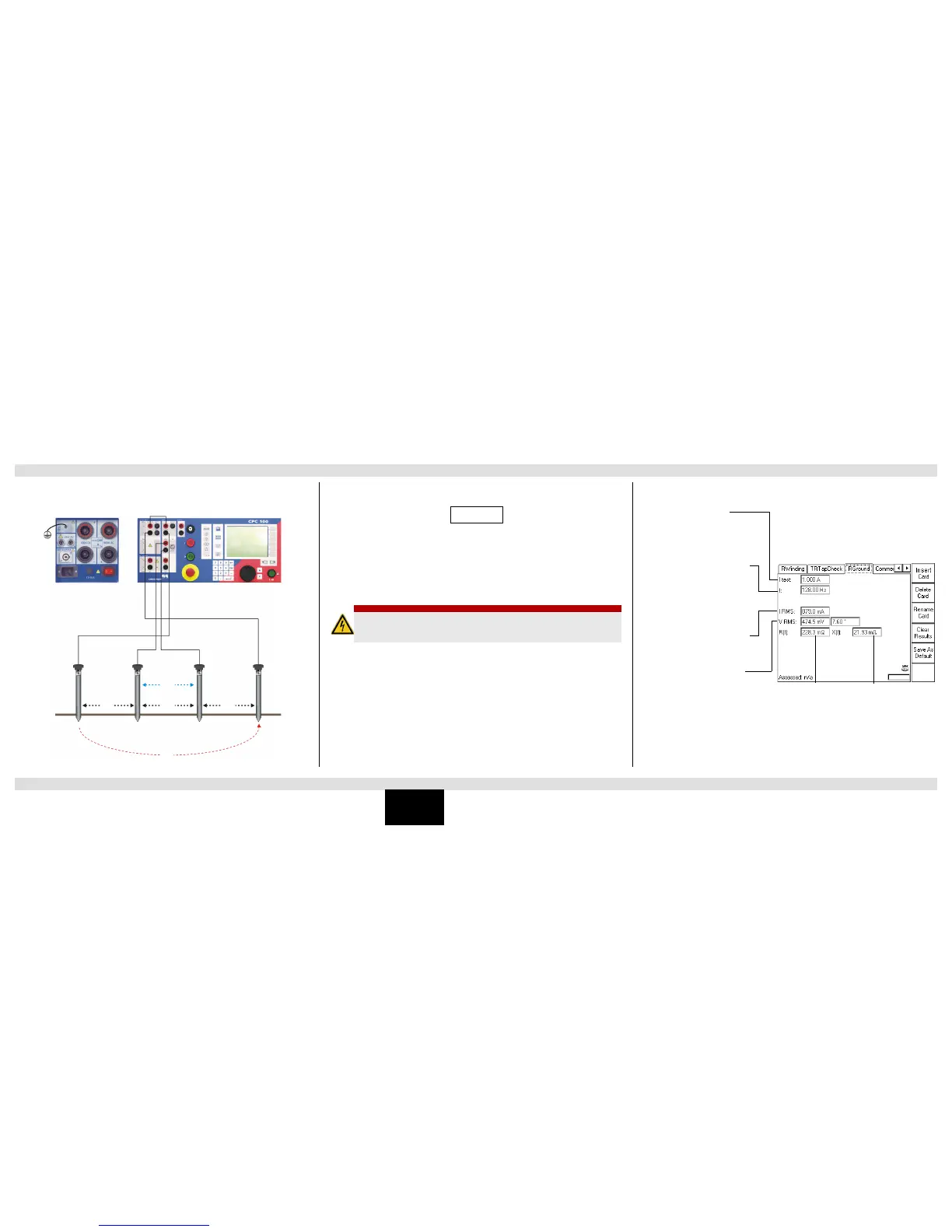
Measuring the Soil Resistivity
Calculating the soil resistivity:
= 2 d R
Legend:
= soil resistivity
d = distance between auxiliary electrodes (identical between all electrodes)
R = calculated resistance as indicated at the RGround test card (R(f))
With the spacing of “d”, the test measures the average soil resistivity between the U auxiliary
electrodes down to a depth of “d”. Therefore, varying “d” also varies the depth of the volume for
which the soil resistivity is to be measured.
Note: To learn how to measure the resistance of a single ground rod in an earthing system, refer
to the CPC 100 Reference Manual, section “RGround” of chapter “Resistance”. The CPC 100
Reference Manual is available in PDF format on the CPC 100 Toolsets or the
CPC 100 Start Page.
DANGER
Death or severe injury caused by high voltage or current
► Do not touch the 6A AC output. It can carry a life-threatening voltage level at high
loop impedances or open measuring circuits.
Nominal test current
Frequency of test current. Select a
frequency other than the 50 or 60Hz
mains frequency to prevent
interferences by stray earth
currents.
Actual test current (rms value)
Measured voltage between
substation ground and the auxiliary
electrode U (rms value, non-
selective frequency) and phase shift
between VRMS and IRMS.
Calculated ohmic part of
earth impedance
(frequency-selective
measurement)
Calculated inductive
part of earth impedance
(frequency-selective
measurement)

 Loading...


