CP TD1
CP TD1 - 3
When using the CP CAL1 for calibration, we recommend to take C1 as reference and to select
the calibration frequency in a range between 50 … 200 Hz.
1. Switch off the CPC 100 at the main power switch.
2. With trolley:
Properly connect the CPC 100 and CP TD1 grounding terminals to the trolley’s ground bar.
Connect the ground bar to earth. All cables minimum 6 mm².
Without trolley:
Properly connect the CPC 100 and CP TD1 grounding terminals to earth. Both cables
minimum 6 mm².
3. Connect the CP TD1’s "BOOSTER IN" to the CPC 100’s "EXT. BOOSTER" with the
OMICRON electronics supplied booster cable.
4. Connect the CP TD1’s "SERIAL" to the CPC 100’s "SERIAL" with the OMICRON electronics
supplied data cable. This cable also provides the power supply for the CP TD1.
5. Pull out the measuring cables from the cable drum and connect the test object to the
CP TD1’s measuring inputs IN A and IN B.
6. Pull out the high-voltage cables from the cable drum and connect the test object to the
CP TD1’s high-voltage output.
7. Switch on the CPC 100.
8. Selecting the TanDelta test card from any of the CPC 100’s CT, VT, Transformer or Others
test card groups automatically turns on the CP TD1. If no CP TD1 is connected to the
CPC 100, an error message appears.
9. Set up your measurement in the TanDelta test card (see page CP TD1-5).
10. Press the CPC 100’s I/O (test start / stop) push-button.
As the first step, before you set a CPC 100 / CP TD1 measurement setup into
operation, link the CPC 100, CP TD1 and, if applicable, the equipment trolley with
a min. 6 mm² grounding cable as displayed on page CP TD1-2.
Never use the CPC 100 / CP TD1 measurement setup without a solid connection
to ground.
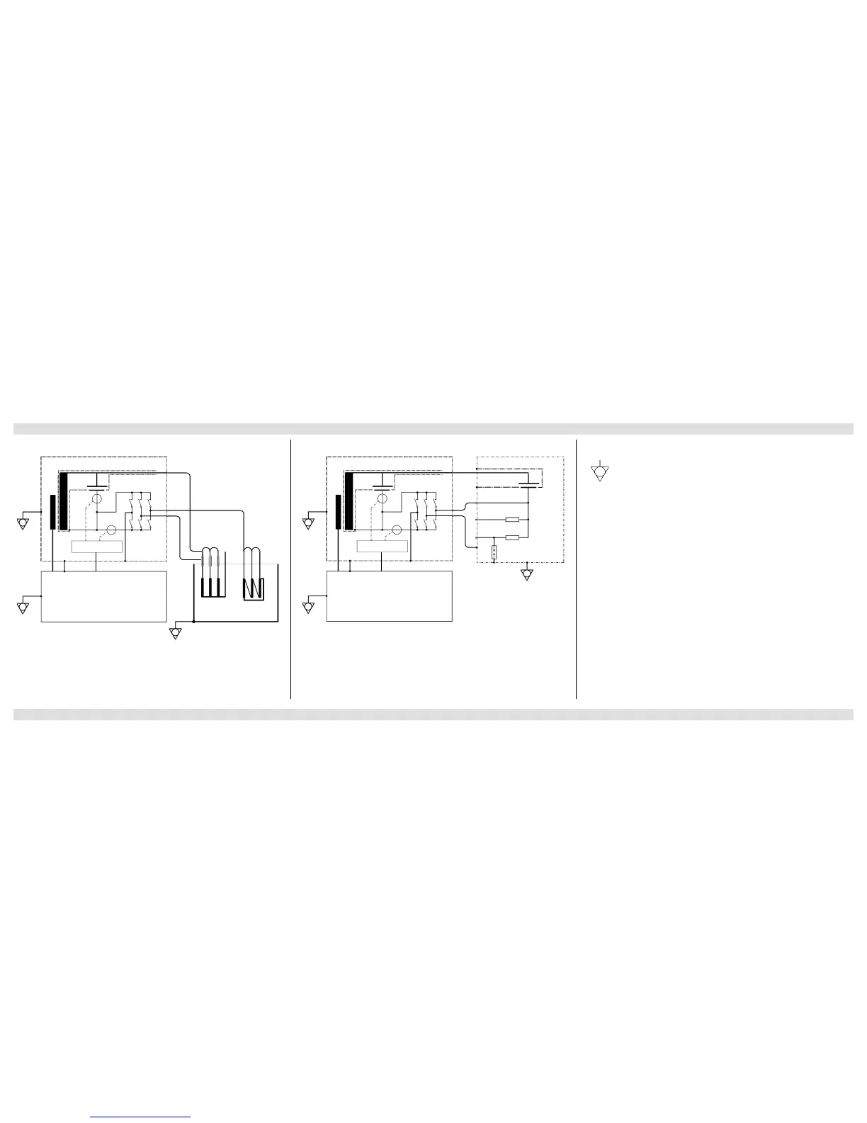
CP TD1 Connected to a Power Transformer CP TD1 Connected to CP CAL1 Putting the CP TD1 into Operation
 Loading...


