EasyManua.ls Logo

Omicron CPC 100 - Line;Ground Impedance Measurement

Omicron CPC 100
77 pages
To Next Page IconTo Next Page
To Previous Page IconTo Previous Page
Loading...
CP CU1
CP CU1 - 5
The following application examples show the typical usage of the CP CU1. The test procedures
running on the measurement setup are controlled by templates available on the
CPC 100 Start Page.
For detailed information on the CP CU1 applications, refer to the CP CU1 Reference Manual
delivered with the CP CU1 or available in pdf format on the CPC 100 Start Page.
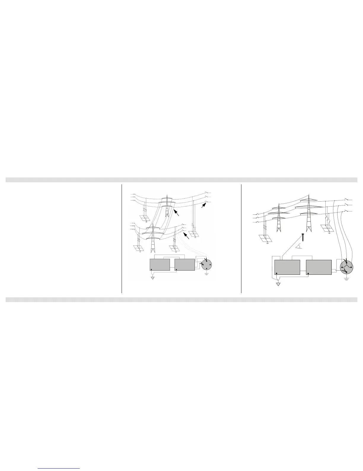
There are seven different measurement loops: A-B (shown here), A-C, B-C, A-G, B-G, C-G and
ABC in parallel to ground (similar to the next figure).
Overhead line
Near end
Far end
V1 AC I AC
CPC 100
EXT. BOOSTER
V1 AC I AC
CPC 100
EXT. BOOSTER
IAC V1AC
CP CU1
BOOSTER
VSENSE
CP GB1
Far end
Overhead line
Near end
IOUT
V1 AC I AC
CPC 100
EXT. BOOSTER
IAC
BOOSTER
IOUT
CP CU1
90°
CP GB1
Applications and Test Templates Line Impedance Measurement Ground Impedance Measurement

Table of Contents

Other manuals for Omicron CPC 100

Related product manuals