CP TD1
CP TD1 - 6
CP TD1
Pressing the Settings button on the TanDelta main page opens the Settings page allowing you
to set additional measurement options.
Filter bandwidth of measurement.
Note: If the test frequency equals the default frequency (as set at Options | Device Setup),
the filter bandwidth is always ± 5 Hz, regardless of the set value. This even applies if the option
"use default frequency of xx.xx Hz" is not specifically selected.
± 5 Hz means that interferences at frequencies with an offset of
± 5 Hz from the measuring
frequency will not affect the results.
The smaller the filter bandwidth, the longer the measuring time.
The averaging factor determines the
number of measurements. A factor of 3
means: the CP TD1 carries out 3
measurements whose results are then
averaged. The higher the factor, the
more accurate the measurement but
the longer the measuring time.
Compound measurement setting
Cp, DF (tan) = parallel capacitance & dissipation factor
Cp, PF (cos) = parallel capacitance & power factor
Cp, Ptest = parallel capacitance & power
Cp, P@10kV = parallel capacitance & power; linearly interpolated to 10 kV test voltage
Qtest, S test = reactive & apparent power
Z = impedance with phase angle
Cp, Rp = parallel capacitance & parallel resistance
Ls, Rs = serial inductance & serial resistance
Cp, QF = parallel capacitance & quality factor
Ls, QF = series inductance & quality factor
If selected, the CPC 100 checks whether the shield of the high-voltage cable is connected. For
some large inductive loads, the CPC 100 can accidentally report shield check error even when
the shield is connected. If this is the case, it makes sense to clear the check box.
If selected, the beeper sounds during
the entire test. If cleared, the beeper
sounds at the beginning and the end of
the test only.
At "Assessment Limits", set the tolerance of the
main page’s nominal values for the assessment.
For the capacitance, the tolerance is entered in
percent, for the dissipation factor it’s a multiplier.
Note: Availability and naming of the entry fields
depend on the measuring mode, e.g., DF and PF
are the same entry field.
The CP TD1 leaves OMICRON
electronics factory-calibrated. If a
component needs to be exchanged by a
spare part, the CP TD1 must be re-
calibrated.
To re-calibrate, set the focus onto the
test card tab designation TanDelta and
press Edit Calib to enable the entry
fields:
• Cx = correction factor for C meas
(multiplier)
• DF/ PF + = corrective value added
to dissipation or power factor (can
be + or -)
Note: Enter your name and press
Update Calib to complete the re-
calibration.
See also figure CP TD1
CP CAL1 on
page CP TD1-3.
Select if you use an external CT.
The entered ratio is used to calculate
the measured current accordingly.
Note: "Use ext. CT" can only be
selected if there are no measurement
results yet.
Returns to TanDelta’s main page
Selecting “Compensations" converts the actually measured dissipation or power factor to
normalized values corresponding to an ambient temperature of 20 ° C. In doing so, the values
entered at "Compensations" represent the existing ambient condition.
► Enter oil temperature, ambient temperature (at bushing) and relative humidity first.
► Then place the cursor on "k".
The medium the measurement takes place in, oil or air, determines the k-factor.
• ANSI C57.12
The oil temperature is the determining medium for the k-factor.
• Bushings
The air temperature at the respective bushing is the determining medium for the k-factor.
Bushings provides three bushing types to select from: RBP (Resin Bonded Paper), RIP
(Resin Impregnated Paper) and OIP (Oil Impregnated Paper). The k-factor changes
accordingly.
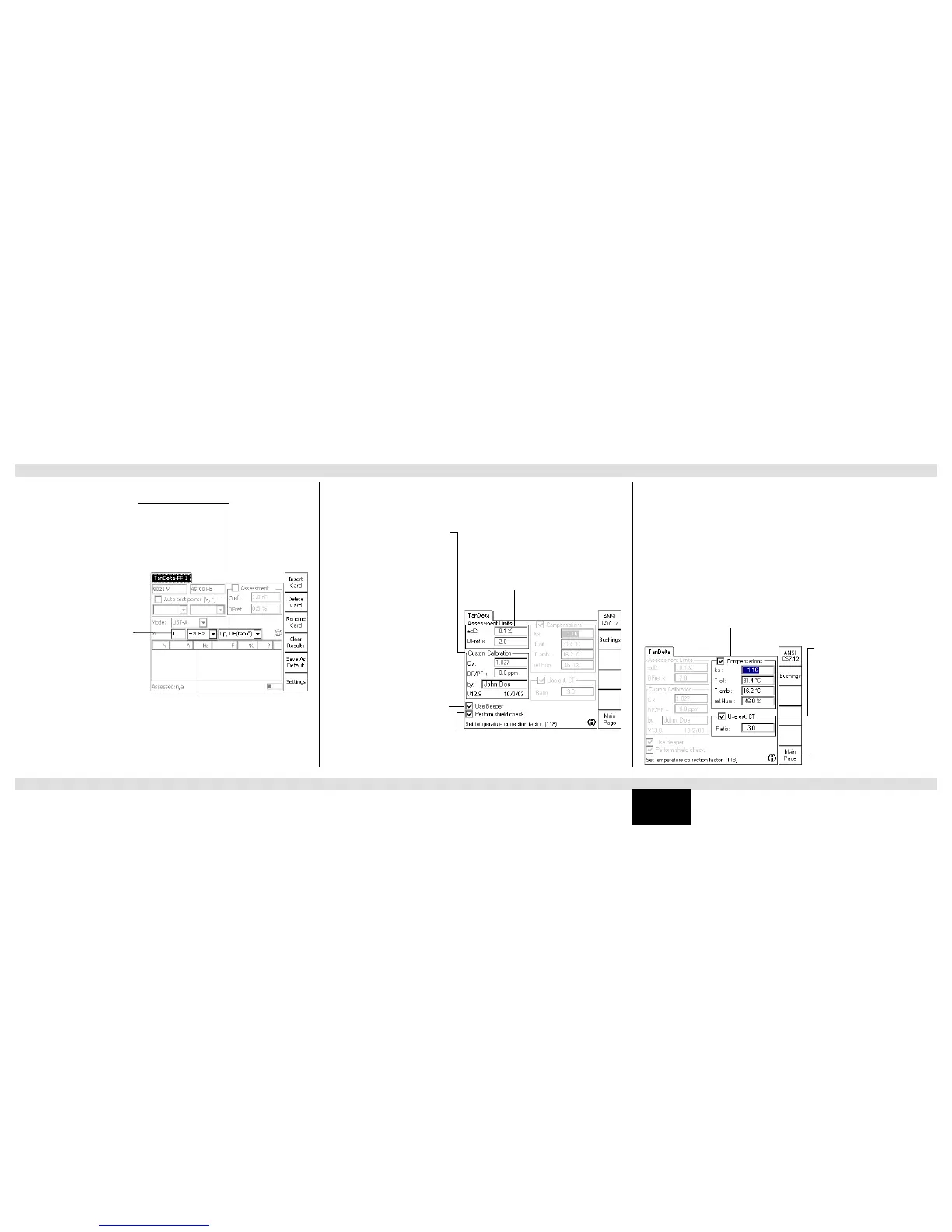
TanDelta-PF Test Card - Main Page TanDelta-PF Test Card - Settings Page

 Loading...


