CPC 100 V 3.20
Preface - 4
Preface
Changing Fuses
► Turn off the CPC 100, unplug the power cord and /or press the Emergency Stop button.
► We recommend to wait for about 30 seconds. This time is necessary for the internal
electrolytic capacitors to fully discharge.
► Ground the test object, and disconnect it from the CPC 100. By disconnecting it, you prevent
a possibly faulty test object feeding power back into the CPC 100.
► Locate the blown fuse on the front panel of the CPC 100, and replace it.
Note: Replace with identical fuse type only (refer to the chapter “Changing Fuses” of the
CPC 100 Reference Manual available in PDF format on the CPC 100 Toolset CD-ROM or the
CPC 100 Start Page).
DC Output to Test Objects with a High Inductance
Use test cards RWinding (winding resistance) and TRTapCheck (tap changer winding
resistance and on-load tap changer interruption check) only:
If a test object with a big inductance was connected to the CPC 100, short-out the test object
additionally before disconnecting it from the CPC 100.
CPC 100 in Combination with the CP TD1
The CP TD1 is an optionally available high-precision test system for on-site insulation tests of
high-voltage systems like power and measuring transformers, circuit breakers, capacitors and
isolators. The CP TD1 works as an add-on device to the CPC 100 and is described in chapter
”CP TD1” of this User Manual.
On principle, the safety instructions that apply to the CPC 100 and its accessories also apply to
the CP TD1. However, the CP TD1 requires some additional precautions and measures. They
are listed in chapter ”CP TD1” on page CP TD1-1.
Different Symbols for PE
The CPC 100 and CP TD1 use different symbols for protective earth (PE):
This is due to a new standard and does not symbolize any functional difference.
Note: Both symbols mean exactly the same, i.e., protective earth (PE) or equipotential ground.
DANGER
Death or severe injury caused by high voltage or current
► Never connect or disconnect test objects and/or cables as long as the on-screen
message “Switch off in progress” is displayed.
► Connect the CP SA1 discharge box to the VDC input sockets when using the
400A DC output to protect yourself and the CPC 100 from high-voltage hazards.
► Use separate clamps for current and voltage connections on both sides of the test
object to avoid hazards in case one clamp falls off during the test.
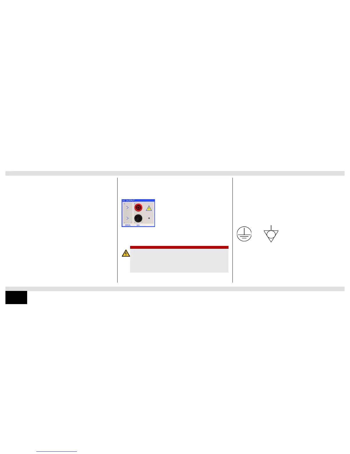
The message Switch off in progress notifies you that, after the
CPC 100 was switched off, the connected external inductance
(i.e., the test object) still “feeds” voltage potential back into the
6A DC or 400A DC output.
The existence of this voltage potential at the 6A DC output is
also indicated by a lit LED - even if the CPC 100 is switched off.
If a test object with a big inductance is connected to the
CPC 100, ground the test object on both ends before
disconnecting it from the CPC 100.

 Loading...


