CPC 100 V 3.20
Others: HV Resonance Test System - 8
Others: HV
Resonance
The HV Resonance Test System test card is used for generic high-voltage tests on GIS with
a resonance circuit in combination with the CP RC1 or the CP RC2.
Note: Refer to the CP RC1 and CP RC2 User Manuals for information on the correct test setup
and connection.
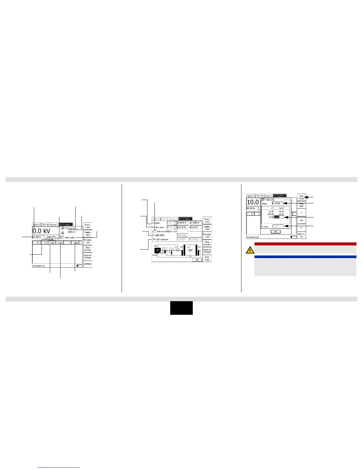
To set the test cycle:
Test settings
Controlled input
channel
Set frequency
value
Set output voltage
Estimated VT ratioAutomatic search of resonance
frequency
Define/set automatic
test cycle
Output voltage at
CPC 100 Ext. Booster
output
Output current at
CPC 100 Ext. Booster
output
Time elapsed for this measurement
Nominal CT ratio
according to CT
nameplate
Nominal VT ratio
according to VT
nameplate
Select if no measurement
VT is available
Short-circuit
impedance of
the power VT
at 100 Hz
Estimated
power VT ratio
with losses
DANGER
Death or severe injury caused by high voltage
► Do not connect a reactor in serial with the CP TR7/CP TR8 output.
NOTICE
Equipment damage caused by high test current
► Verify that the voltage transformer used for the high-voltage generation can
withstand the needed test current.
► Observe the maximum operating time of the VT and the CP RC1. Refer to the
corresponding manuals for more information.
Indicates the voltage slope between
the states
State definition
Total time of test cycle
Press to add state
General Test Settings
Others: HV Resonance Test System

 Loading...


