CPC 100 V 3.20
CPC 100 Technical Data - 2
CPC 100
Technical Data
All input/output values are guaranteed over one year within an ambient temperature of 23 °C ±
5 ° (73 °F ± 10 °F), a warm-up time longer than 25 min and in a frequency range of 45 … 60 Hz
or DC. Accuracy values indicate that the error is smaller than ± (value read x reading error + full
scale of the range x full scale error).
1. With a mains voltage of 230 V using a 2 x 6 m high-current cable at an ambient temperature
of 23°C ± 5° (73°F ± 10°F)
2. Signals below 50 Hz or above 60 Hz with reduced values possible.
3. Output can be synchronized with V1 AC in Quick, Sequencer, Ramping and Amplifier.
4. The input / output is protected with lightning arrestors between the connector and against
protective earth. In case of energy above a few hundred Joule the lightning arrestors apply
a permanent short-circuit to the input / output.
5. Signals below 50 Hz or above 200 Hz with reduced values possible.
6. 98 % of all units have an accuracy better than specified as typical.
7. Input is galvanically separated from all other inputs
8. V1 and V2 are galvanically coupled but separated from all other inputs.
9. There are power restrictions for mains voltages below 190V AC.
10. Fuse-protected
11. When using the CTRogowski test card, the 3V V2 AC input uses an additional software
based integration method. In the range of 50 Hz < f < 60 Hz, this results in a phase shift of
90° as well as an additional phase error of +/- 0.1° and an additional amplitude error of +/-
0.01 %. For frequencies in the range of 15 Hz < f < 400 Hz, the phase error is not specified,
and the amplitude error can be up to +/- 0.50 % higher.
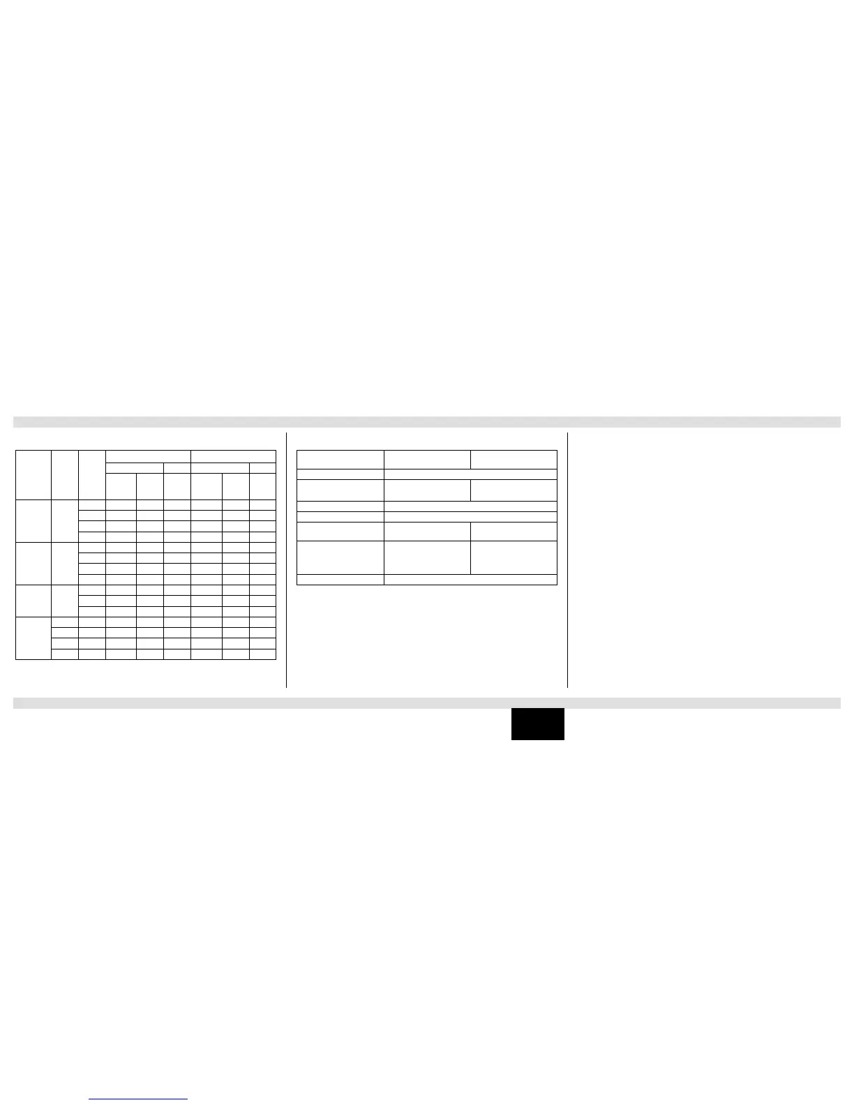
Input Imped. Range
Guaranteed accuracy
Typical accuracy
6
Amplitude Phase Amplitude Phase
Reading
error
Full
scale
error
Full
scale
error
Reading
error
Full
scale
error
Full
scale
error
IAC/DC
4, 7
<0.1
10A AC 0.10 % 0.10 % 0.20° 0.05 % 0.05 % 0.10°
1A AC 0.10 % 0.10 % 0.30° 0.05 % 0.05 % 0.15°
10A DC 0.05 % 0.15 % - 0.03 % 0.08 % -
1A DC 0.05 % 0.15 % - 0.03 % 0.08 % -
V1 AC
8
500 k
300 V 0.10 % 0.10 % 0.20° 0.05 % 0.05 % 0.10°
30 V 0.10 % 0.10 % 0.20° 0.05 % 0.05 % 0.10°
3 V 0.20 % 0.10 % 0.20° 0.10 % 0.05 % 0.10°
300 mV 0.30 % 0.10 % 0.20° 0.15 % 0.05 % 0.10°
V2 AC
8, 11
10 M
3 V 0.05 % 0.15 % 0.20° 0.03 % 0.08 % 0.10°
300 mV 0.15 % 0.15 % 0.20° 0.08 % 0.08 % 0.10°
30 mV 0.20 % 0.50 % 0.30° 0.10 % 0.25 % 0.15°
VDC
4, 7
10 V 0.05 % 0.15 % - 0.03 % 0.08 % -
1 V 0.05 % 0.15 % - 0.03 % 0.08 % -
100 mV 0.10 % 0.20 % - 0.05 % 0.10 % -
10 mV 0.10 % 0.30 % - 0.05 % 0.15 % -
Test cards Quick,
Sequencer, Ramping
Test card Amplifier
Frequency range 48 … 62 Hz
Synchronization inputs V1 AC
(automatic range switching)
V1 AC, V2 AC, I AC
(fixed to maximum range)
Input magnitude 10 % of input range full scale
Output magnitude 5 % of output range full scale
Settling time 100 ms after 5 % of output
magnitude is reached
1000 ms after 5 % of output
magnitude is reached
Signal changes All quantities must be ramped
within 20 signal periods
No changes of frequency and
phase. Magnitude changes
without limitation. Output
follows within 250 ms.
Phase tolerance 0.5° within the limits as specified above
Measuring Inputs Output to Input Synchronization Notes Related to Inputs and Outputs

 Loading...


