CPC 100 V 3.20
Others: Ramping - 4
Others:
Ramping
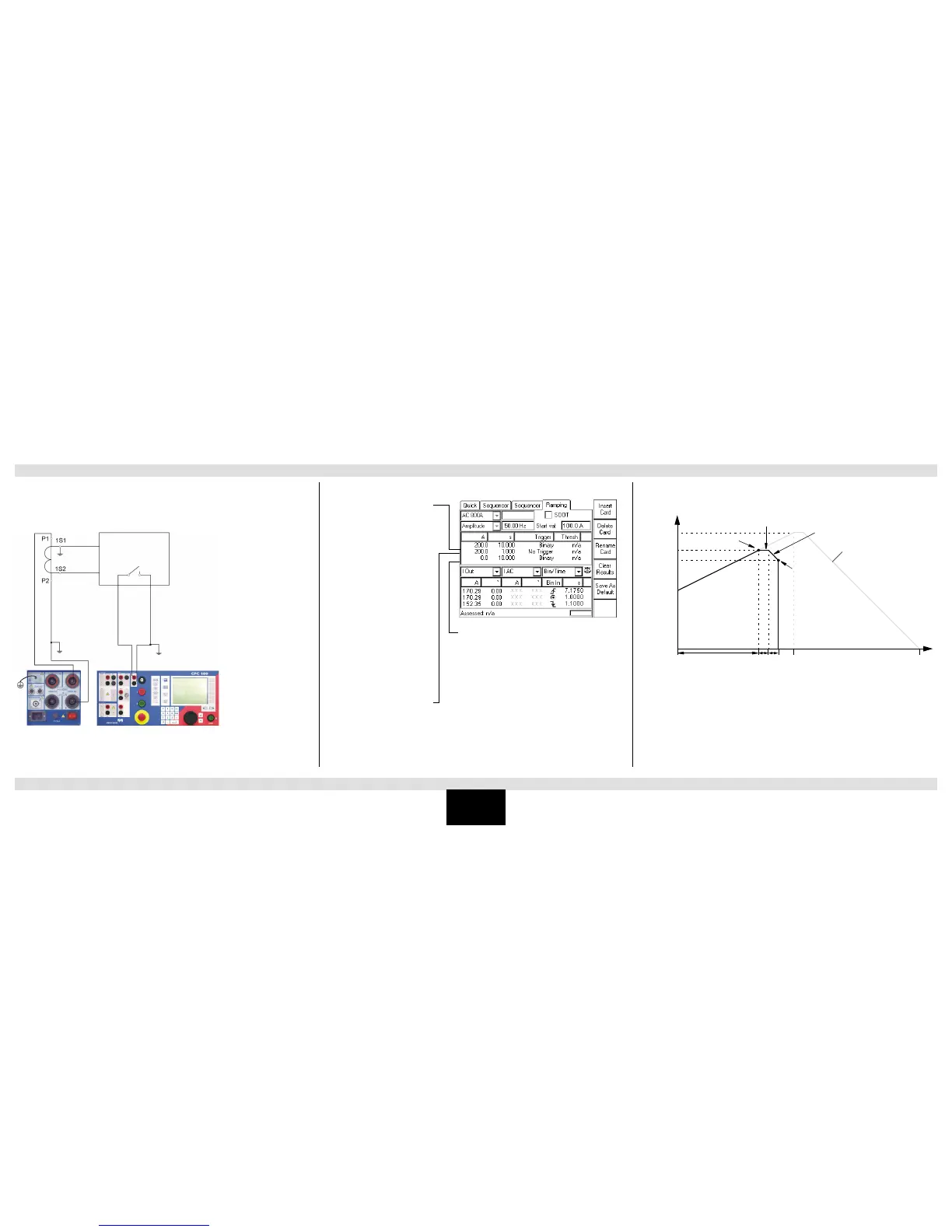
To determine the pick up and the drop off value of a relay, a series of three ramps is defined.
The first ramp determines the pick up value, the second one represents a 1 s pause time, and
the third ramp determines the drop off value.
The CPC 100’s AC OUTPUT feeds the ramped current signal into a CT, which is connected to
an overcurrent relay. The overcurrent relay’s trip contact is fed into the CPC 100’s binary input
BinIn, and acts there as a trigger signal.
Time sequence of the three ramps:
Ramp 1:
Set to output a ramped current
signal from 100.0A to either 200.0A
in 10s, or until the trigger condition
"Binary" occurs.
Here, trigger condition "Binary"
means: the relay contact picks up. In
this moment, ramp 1 terminates and
the series continues with ramp 2.
The measurement table shows for
ramp 1 that the relay contact picked
up after 7.175s at a current value of
170.29A
Ramp 3:
Because ramp 1 did not reach the 200A due to the
trigger signal, ramp 3 starts with 170.29 A, and then
ramps down to zero with the set steepness (200.0A to
0.0A in 10s) until the trigger condition "Binary" occurs.
Here, trigger condition "Binary" means: the relay
contact drops off. Since there are no further ramps
defined, in this moment the sequence terminates.
The measurement table shows for ramp 3 that the relay
contact dropped off 1.1s after ramp 3 started at a
current value of 152.35 A.
Ramp 2:
Pause time. Test current output is
"frozen" for 1 s.

 Loading...


