CP CU1
CP CU1 - 3
The CPC 100 must be configured for the CP CU1. Follow the steps below to configure the
CPC 100:
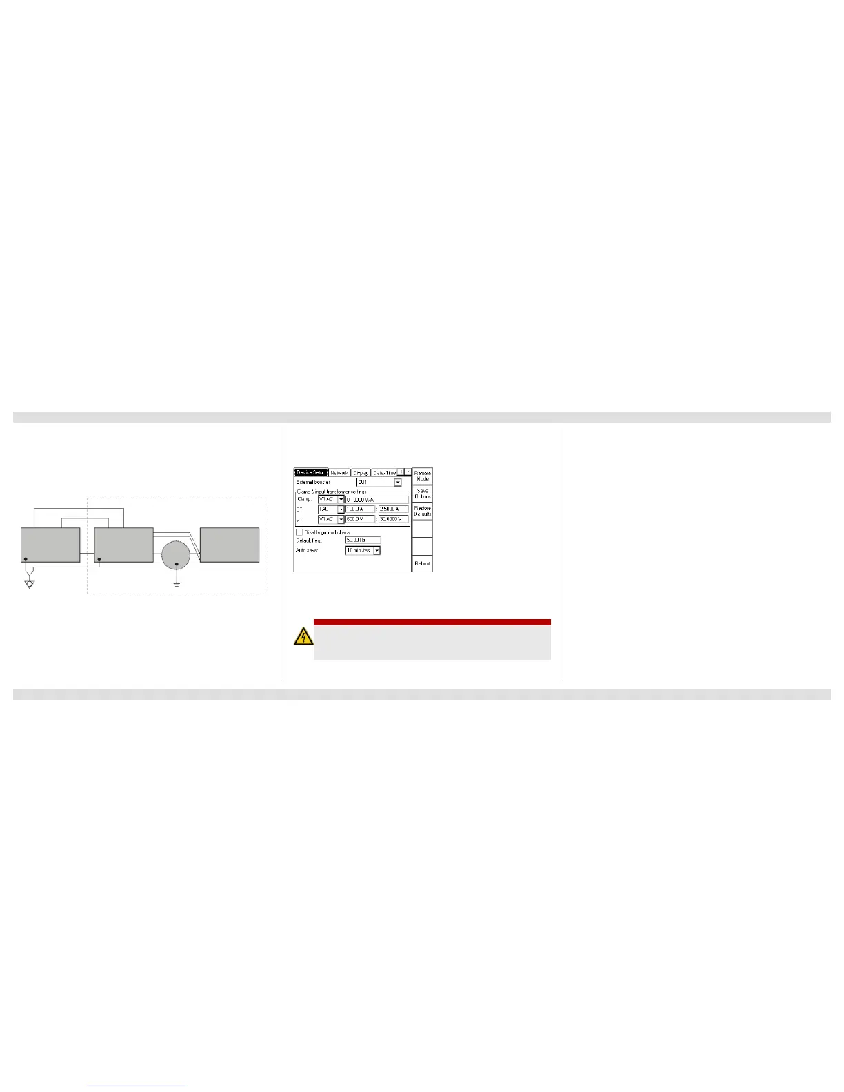
1. Press the Options view selector button to open the Options window.
2. In the External booster combo box, select CU 1.
The CT and VT settings are set according to the built-in current and voltage transformers
automatically.
3. Set the current range of the CP CU1 using the current range switch (see page CP CU1-2)
to the value configured by the CPC 100 software.
Note: Current range settings on the test card and on the CP CU1 front panel must be the same.
Safety Instructions
► Do not connect the measurement setup to overhead lines if there is a possibility of a
thunderstorm over any part of the lines to be measured. A lightning discharge to the line
under test can cause injury or possibly death of the operating staff.
► It is strongly recommended to take all parallel lines out of service before proceeding.
Connecting the measurement setup to overhead lines with a life parallel system brings about
high-voltage hazards.
► While the grounding switch at the near end of the power line is open, the area around the
CP GB1 in the range of 5 m/15 ft and around the CP CU1 in the range of 2 m/5 ft is a
dangerous zone due to high-voltage and mechanical hazards. Do not enter the dangerous
zone. Keep the grounding switch open for a time as short as possible.
► If you see or hear anything uncommon in the test equipment, e.g. noise of electrical
discharge or lightening of surge arrestors, close the grounding switch before touching the
measurement setup.
DANGER
Death or severe injury caused by high voltage or current
► Only set the current range switch on the CP CU1 front panel when the CPC 100 is
turned off and the test object is connected to ground with closed grounding switch
near the measurement setup.
Measurement Setup Configuring the CPC 100 Connecting the CPC 100 and CP CU1 to Power Lines

 Loading...


