432
Conversion Instructions Section 3-11
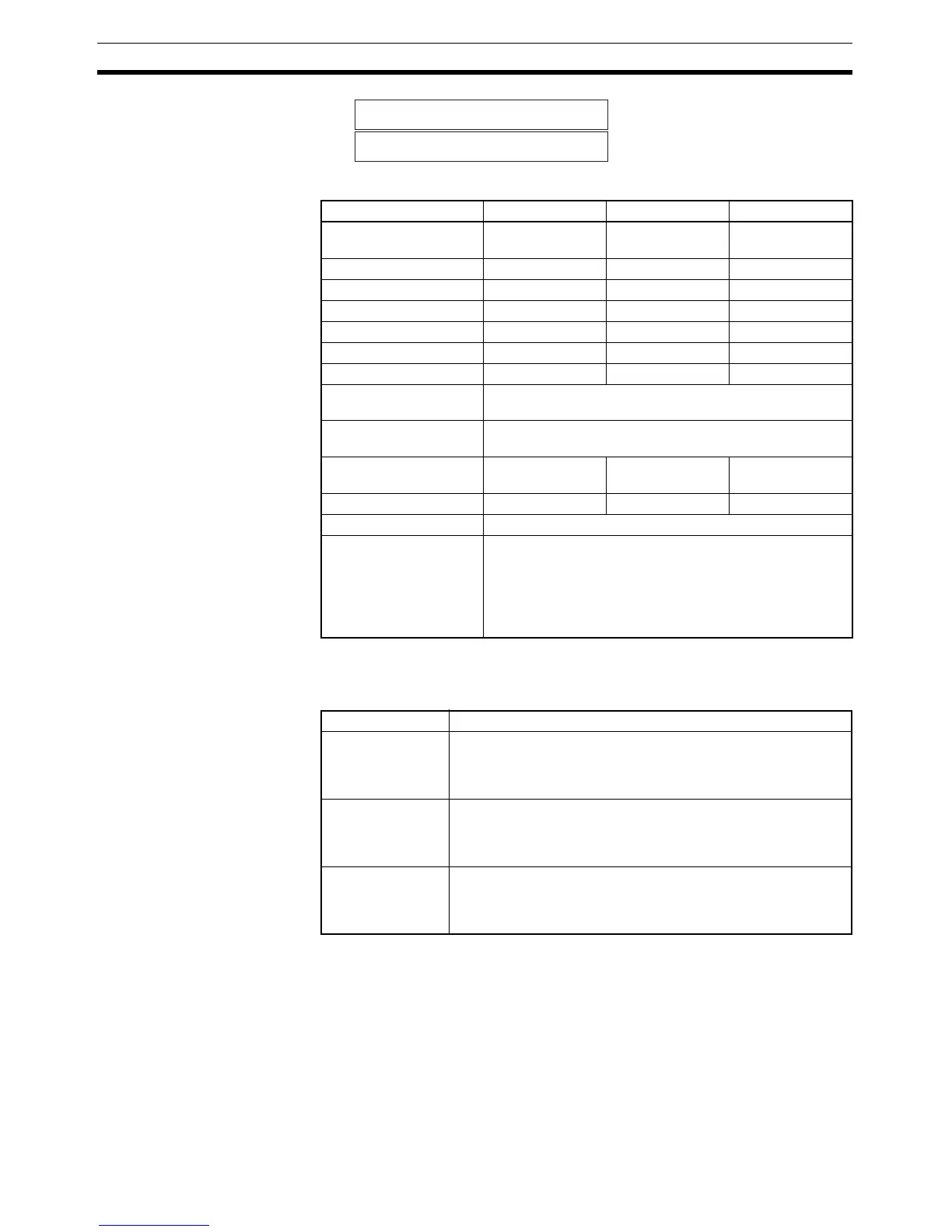
Operand Specifications
Description GRY(474) converts the gray binary code in the word specified in S at the res-
olution specified in C using one of the following conversion modes (binary,
BCD, or 360
°), also specified in C, and places the results in D and D+1.
Note (1) GRY(474) is normally used when inputting, through a DC Input Unit, a
parallel signal (2
n
) from an absolute encoder that outputs a gray binary
code.
(2) If the word specified for S is allocated to an Input Unit, the input data con-
verted by GRY(474) will be for the gray binary code from the previous
CPU Unit cycle, i.e., it will be one cycle time old.
D
D+1
Rightmost word
Leftmost word
Area C S D
CIO Area CIO 0 to
CIO 6141
CIO 0 to
CIO 6143
CIO 0 to
CIO 6142
Work Area W0 to W509 W0 to W511 W0 to W510
Holding Bit Area H0 to H509 H0 to H511 H0 to H510
Auxiliary Bit Area A0 to A957 A0 to A959 A448 to A958
Timer Area T0000 to T4093 T0000 to T4095 T0000 to T4094
Counter Area C0000 to C4093 C0000 to C4095 C0000 to C4094
DM Area D0 to D32765 D0 to D32767 D0 to D32766
Indirect DM addresses
in binary
@ D0 to @ D32767
Indirect DM addresses
in BCD
*D0 to *D32767
Constants --- #0000 to #FFFF
(binary)
---
Data Registers --- DR0 to DR15 ---
Index Registers ---
Indirect addressing
using Index Registers
,IR0 to ,IR15
–2048 to +2047 ,IR0 to –2048 to +2047 ,IR15
DR0 to DR15, IR0 to IR15
,IR0+(++) to ,IR15+(++)
,–(– –)IR0 to, –(– –)IR15
Conversion mode Function
Binary Mode Gray binary code is converted to binary data between
0000 0000 and 0000 7FFF hex. Zero point offset and remainder
compensation is applied and then the result is output to D and
D+1.
BCD Mode Gray binary code is converted to BCD data. Zero point offset
and remainder compensation is applied, the data is converted
to BCD between 0000 0000 and 0003 2767, and then the result
is output to D and D+1.
360° Mode Gray binary code is converted to BCD data. Zero point offset
and remainder compensation is applied, the data is converted
to an angle between 0000 0000 and 0000 3599 (0.0° to 359.9°
in 0.1° increments), and then the result is output to D and D+1.