433
Conversion Instructions Section 3-11
Flags
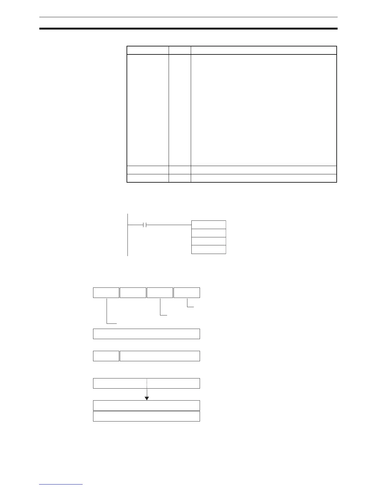
Examples When CIO 0.00 is ON in the following example, the gray binary code in
CIO 1000 is converted according to the settings in the control data in D0 to D2
and the result is output to D200.
■ Example 1: Converting to Binary Data with an 8-bit Resolution and Zero
Point Offset of 001A Hex
Name Label Operation
Error Flag ER ON if bits 12 to 15 of C are not 0 hex (operating mode =
gray binary code conversion).
ON if the zero point offset in C+1 is not within the specified
resolution (including user-specified resolutions).
ON if bits 04 to 07 of C are not 0 hex (= Binary Mode),
1 hex (= BCD Mode), or 2 hex (= 360° Mode).
ON if the specified encoder remainder compensation
exceeds the set user-specified resolution when bits 00 to
03 of C are 0 hex (= user-specified resolution).
ON if the converted binary value is less than the encoder
remainder compensation when bits 00 to 03 of C are 0 hex
(= user-specified resolution).
ON if the converted binary value is less than the resolution
when bits 00 to 03 of C are 0 hex (= user-specified resolu-
tion).
OFF in all other cases.
Equals Flag = OFF in all cases.
Negative Flag N OFF in all cases.
GRY
1000
D0
D200
0.00
C
S
D
0 0
C: D0
0
80
4 3 7 8111215
001A
C+1: D1
S: 1000 1001010000000000
0017
D: D200
0000
D+1: D201
000
C+2: D2
0
Operating mode: Gray binary code conversion
Conversion mode: Binary Mode
Resolution: 8-bit
Zero point offset: 001A hex
User-specified resolution: Not used.
Gray binary code
Converted and offset.
Result of binary conversion and offsetting stored.