71
Specifications Section 2-2
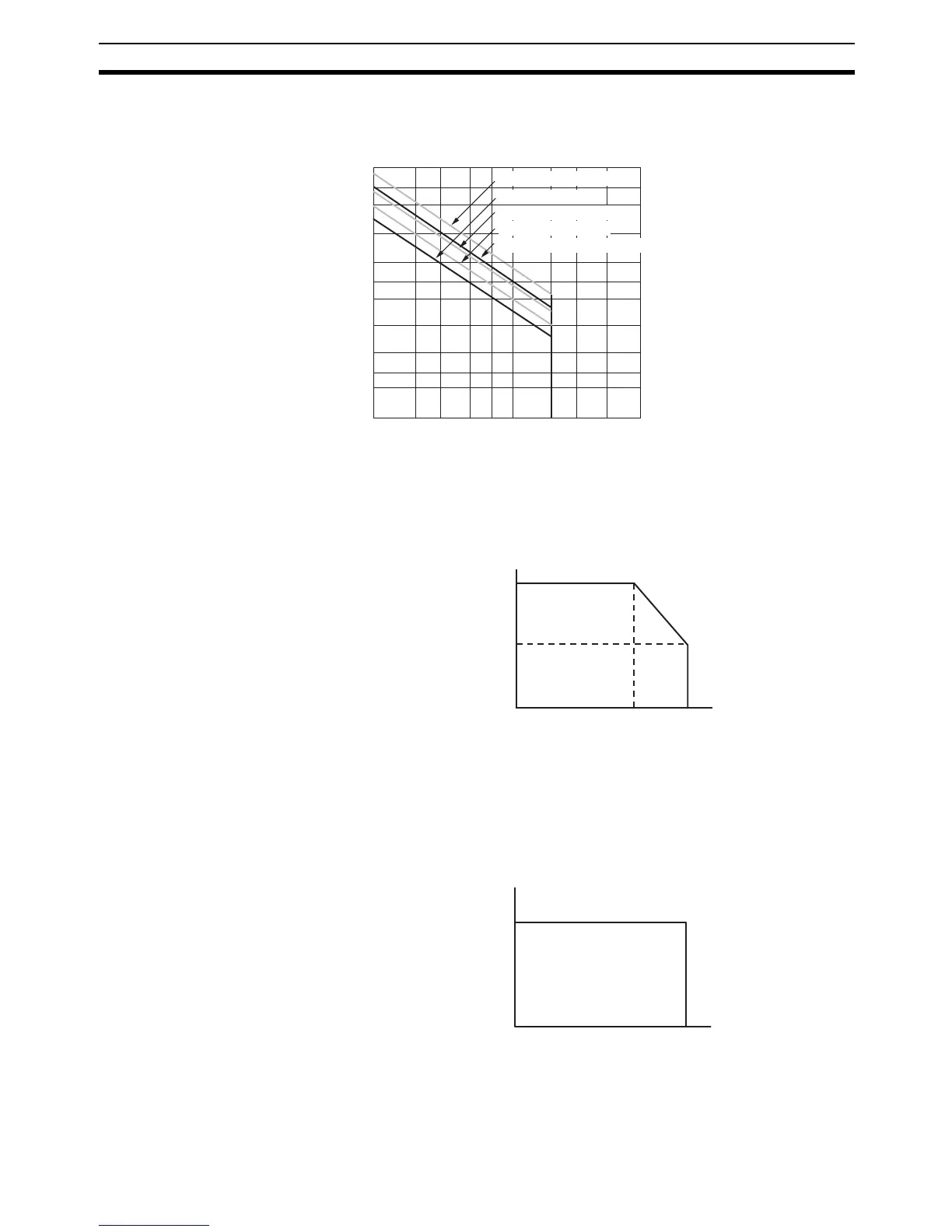
Note (1)Under the worst conditions, the service life of output contacts is as shown
above. The service life of relays is as shown in the following diagram as a
guideline.
(2)With the CPM1A-16ER/CP1W-32ER/CP1W-16ER, the load current is
restricted depending on the ambient temperature. Design the system con-
sidering the load current based on the following graph.
(3)CP1W-32ER’s maximum number of simultaneously ON output points is 24
(75%). Design the system considering the simultaneously ON points and
load current based on the following curve.
300
200
100
50
30
20
5
3
2
10
0.1
0.2 0.3 0.5 0.7 1 2 3 5
Life (× 10
4
)
Contact current (A)
120 VAC resistive load
24 VDC τ = 7 ms
120 VAC cosφ = 0.4
24 VDC cosφ = 0.4
24 VDC/240 VAC resistive load
Switching rate: 1,800 operations/hou