112
Mounting Section 3-3
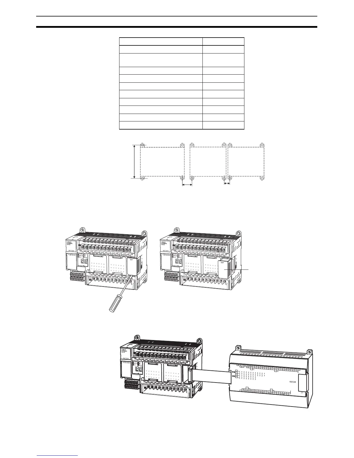
Space between Units When Expansion I/O Units Are Connected
1,2,3... 1. Remove the cover from the CPU Unit's or the Expansion I/O Unit's expan-
sion connector. Use a flat-blade screwdriver to remove the cover from the
Expansion I/O Connector.
2. Insert the Expansion I/O Unit's connecting cable into the CPU Unit's or the
Expansion I/O Unit's expansion connector.
Unit A (mm)
CP1H CPU Unit 140 ±0.5
Expansion I/O Unit, 32 or 40 I/O
points
140 ±0.2
Expansion I/O Unit, 20 I/O points 76 ±0.2
Expansion I/O Unit, 16 outputs 76 ±0.2
Expansion I/O Unit, 8 inputs 56 ±0.2
Expansion I/O Unit, 8 outputs 56 ±0.2
Analog I/O Unit 140 ±0.5
Temperature Sensor Unit 76 ±0.2
CompoBus/S I/O Link Unit 56 ±0.2
DeviceNet I/O Link Unit 56 ±0.2
100 mm
20 mm min.
25 mm max.
10 mm min.
15 mm max.
CP1H CPU Unit
Expansion I/O Unit
Expansion Unit
Expansion I/O Unit
Expansion Unit
Expansion
connector cover