122
Wiring CP1H CPU Units Section 3-4
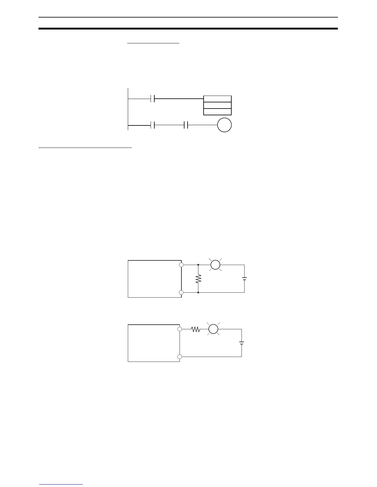
Program Example
In this example, the sensor's power supply voltage is provided to input bit CIO
0.00 and a 100-ms timer delay (the time required for an OMRON Proximity
Sensor to stabilize) is created in the program. After the Completion Flag for
the timer turns ON, the sensor input on input bit CIO 0.01 will cause output bit
CIO 100.00 to turn ON.
Output Wiring Precautions
Output Short-circuit
Protection
If a load connected to the output terminals is short-circuited, output compo-
nents and the printed circuit boards may be damaged. To guard against this,
incorporate a fuse in the external circuit. Use a fuse with a capacity of about
twice the rated output.
Connecting to a TTL
Circuit
A TTL circuit cannot be connected directly to a transistor output because of
the transistor's residual voltage. It is necessary to connect a pull-up resistor
and a CMOS IC between the two.
Inrush Current
Considerations
When connecting a transistor or triac output to a load having a high inrush
current (such as an incandescent lamp), steps must be taken to avoid dam-
age to the transistor or triac. Use either of the following methods to reduce the
inrush current.
TIM
100
#0001
0.00
100.00
0.01T100
OUT
R
COM
L
+
OUT
R
COM
L
+
SYSMAC CP1H
SYSMAC CP1H
Example Method 1
Example Method 2
Use a dark current of approximately 1/3 the rated current of the incandescent lamp.
Install a limit resistance.