131
Wiring Methods Section 3-5
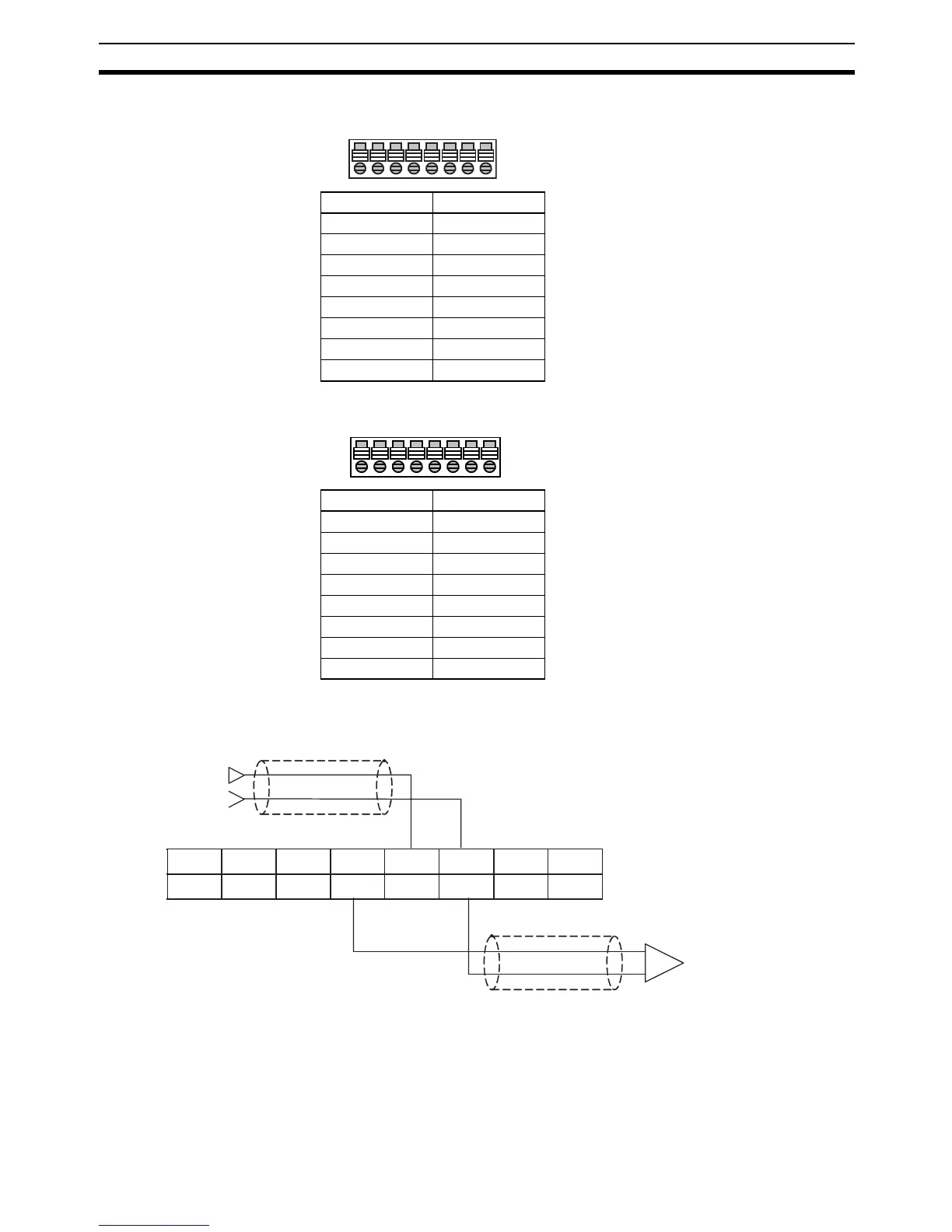
Analog Input Terminal Block
8
Analog Output Terminal Block
8
Note Do not connect the shield.
Analog I/O Wiring Example
Note (1) When using a current input, turn ON voltage/current input switch pins IN1
to IN4, and make the suitable setting in the PLC Setup.
(2) For any inputs that are not to be used, set them to not be used by clearing
the selection of the Use checkbox.
If an input that is set to be used is not actually used, the data for that input
may be unstable. If that occurs, the instability can be removed by short-
Pin Function
1IN1+
2IN1−
3IN2+
4IN2−
5IN3+
6IN3−
7IN4+
8IN4−
A/D
1345678
2
Pin Function
9OUT V1+
10 OUT I1+
11 OUT1−
12 OUT V2+
13 OUT I2+
14 OUT2−
15 IN AG*
16 IN AG*
D/A
910111213141516
+
−
IN1+
IN1−
IN2+
IN2−
IN3+
IN3−
IN4+
IN4−
OUTV1+ OUTI1+
OUT1−
OUTV2+ OUTI2+
OUT2−
IN AG IN AG
Input 3
Shield
Shield
Output 3
(voltage output)