200
Interrupt Functions Section 5-1
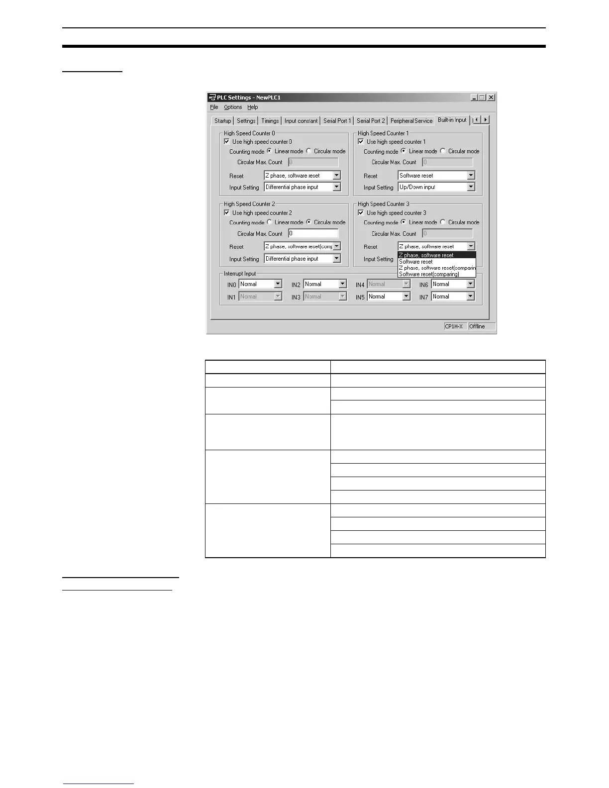
PLC Setup Click the Built-in Input Tab to and set the high-speed counters that will be
used for interrupts.
PLC Setup
High-speed Counter
Terminal Allocation
The following diagrams show the input terminals that can be used for high-
speed counters in each CPU Unit.
Item Setting
Use high speed counter 0 to 3 Use counter
Counting mode Linear mode
Circular mode (ring mode)
Circular Max. Count 0 to FFFF FFFF hex
(When circular (ring) mode is selected as the count-
ing mode, set maximum ring value here.)
Reset method Phase Z and software reset
Software reset
Phase Z and software reset (continue comparing)
Software reset (continue comparing)
Input Setting Differential phase inputs (4x)
Pulse + direction inputs
Up/Down inputs
Increment pulse input