205
Interrupt Functions Section 5-1
New PV Setting in NV and NV+1
Ladder Program
Examples
Example 1: High-speed
Counter (Linear Mode)
In this example, high-speed counter 0 operates in linear mode and starts
interrupt task 10 when the PV reaches 30,000 (0000 7530 hex).
1,2,3... 1. Set high-speed counter 0 in the PLC Setup’s Built-in Input Tab.
2. Set the target-value comparison table in words D10000 to D10003.
3. Create the program for interrupt task 10. Always put an END(001) instruc-
tion at the program’s last address.
Operand Settings
P Port specifier #0000 to #0003 Pulse outputs 0 to 3
#0010 High-speed counter 0
#0011 High-speed counter 1
#0012 High-speed counter 2
#0013 High-speed counter 3
#0100 to #0107 Input interrupts 0 to 7 (in counter mode)
#1000 or #1001 PWM(891) output 0 or 1
C Control data #0000 Start comparison.
#0001 Stop comparison.
#0002 Change the PV.
#0003 Stop pulse output.
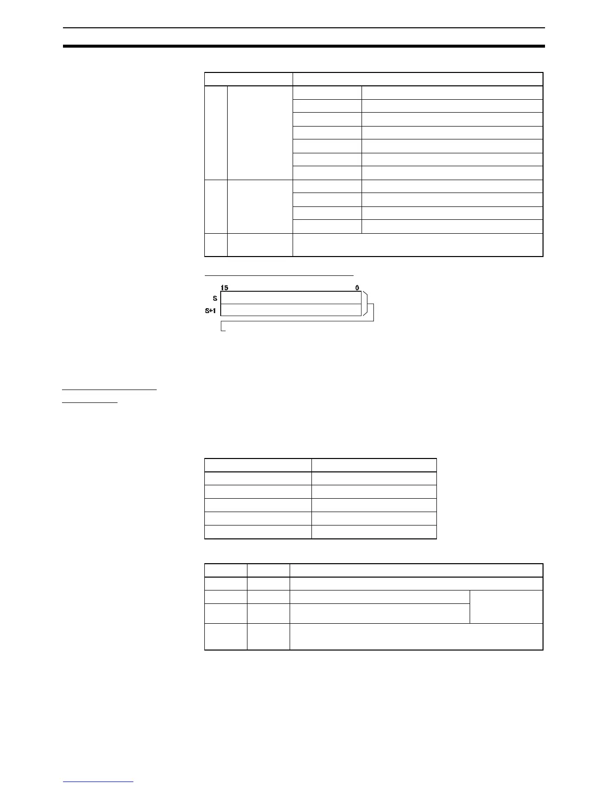
NV First word of
new PV
NV and NV+1 contain the new PV when C is set to #0002
(change the PV).
New PV (rightmost 4 digits)
New PV (leftmost 4 digits)
Setting range for pulse outputs and high-speed counter inputs:
0000 0000 to FFFF FFFF hex
Setting range for input interrupts (counter mode):
0000 0000 to 0000 FFFF hex
Item Setting
High-speed counter 0 Use counter
Counting mode Linear mode
Circular Max. Count ---
Reset method Software reset
Input Setting Up/Down inputs
Word Setting Function
D10000 #0001 Number of target values = 1
D10001 #7530 Rightmost 4 digits of the target value 1 data Target value =
30,000
(0000 7530 hex)
D10002 #0000 Leftmost 4 digits of the target value 1 data
D10003 #000A Bit 15: 0 (incrementing)
Bits 0 to 7: A hex (interrupt task number 10)