222
High-speed Counters Section 5-2
■ PLC Setup
Select the Use high speed counter 0 Option in the PLC Setup’s Built-in Input
Tab.
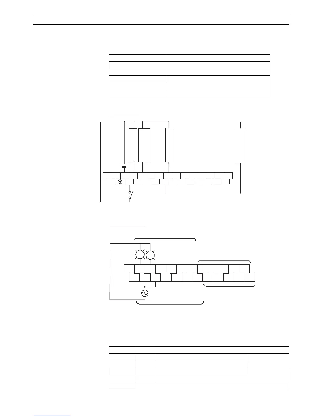
■ I/O Wiring
Input Wiring
Output Wiring
■ Range Comparison Table Settings
The inspection standards data is set in the DM Area with the CX-Programmer.
Even though range 1 is the only range being used, all 40 words must still be
dedicated to the range comparison table.
Item Setting
High-speed counter 0 Use high speed counter 0
Counting mode Linear mode
Circular Max. Count ---
Reset method Software reset
Input Setting Up/Down inputs
L1 L2/N COM 01 03 05 07 09 11 01 03 05 07 09 11
LG
00 02 04 06 08 10 00 02 04 06 08 10
Workpiece end
detection
Counter 0 phase Z
Workpiece start
detection
Counter 0 phase B
Counter 0 phase A
Top
terminal
block
Measurement
start switch
+ 00 01 02 03 0 4 06 00 01 03 04 06
− COM COM COM COM 05 07
COM
02
COM
05 07
CIO 100
CIO 101
CIO 1 00
CIO 101
PL1
PL2
PL1: OK indicator
PL2: NG indicator
Bottom
terminal block
Word Setting Function
D10000 #7430 Rightmost 4 digits of range 1 lower limit Lower limit value:
30,000
D10001 #0000 Leftmost 4 digits of range 1 lower limit
D10002 #765C Rightmost 4 digits of range 1 upper limit Upper limit value:
30,300
D10003 #0000 Leftmost 4 digits of range 1 upper limit
D10004 #000A Range 1 interrupt task number = 10 (A hex)