247
Pulse Outputs Section 5-3
Relationship between the
Coordinate System and
Pulse Specification
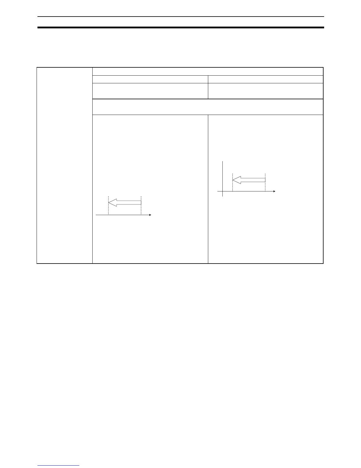
The following table shows the pulse output operation for the four possible
combinations of the coordinate systems (absolute or relative) and the pulse
output (absolute or relative) specified when PULS(886) or PLS2(887) is exe-
cuted.
Pulse output
specified in
PULS(886) or
PLS2(887
Coordinate system
Relative coordinate system Absolute coordinate system
Origin not established:
The No-origin Flag will be ON in this case.
Origin established:
The No-origin Flag will be OFF in this case.
Relative pulse speci-
fication
Positions the system to another position relative to the current position.
Number of movement pulses = number of pulses setting
The pulse output PV after instruction execution
= Number of movement pulses = Number of
pulses setting
Note The pulse output PV is reset to 0 just before
pulses are output. After that, the specified num-
ber of pulses is output.
The following example shows the number of
pulses setting = 100 counterclockwise.
Pulse output PV range:
80000000 to 7FFFFFFF hex
Number of pulses setting range:
00000000 to 7FFFFFFF hex
The pulse output PV after instruction execution
= PV + Number of movement pulses.
The following example shows the number of
pulses setting = 100 counterclockwise.
Pulse output PV range:
80000000 to 7FFFFFFF hex
Number of pulses setting range:
00000000 to 7FFFFFFF hex
100
Number of pulses
setting
II
Number of
movement pulses
Target
position
Current
position=0
Pulse
output PV
100
0
Number of pulses
setting
II
Number of
movement pulses
Target
position
Current
position
Pulse
output PV
Origin