301
Pulse Outputs Section 5-3
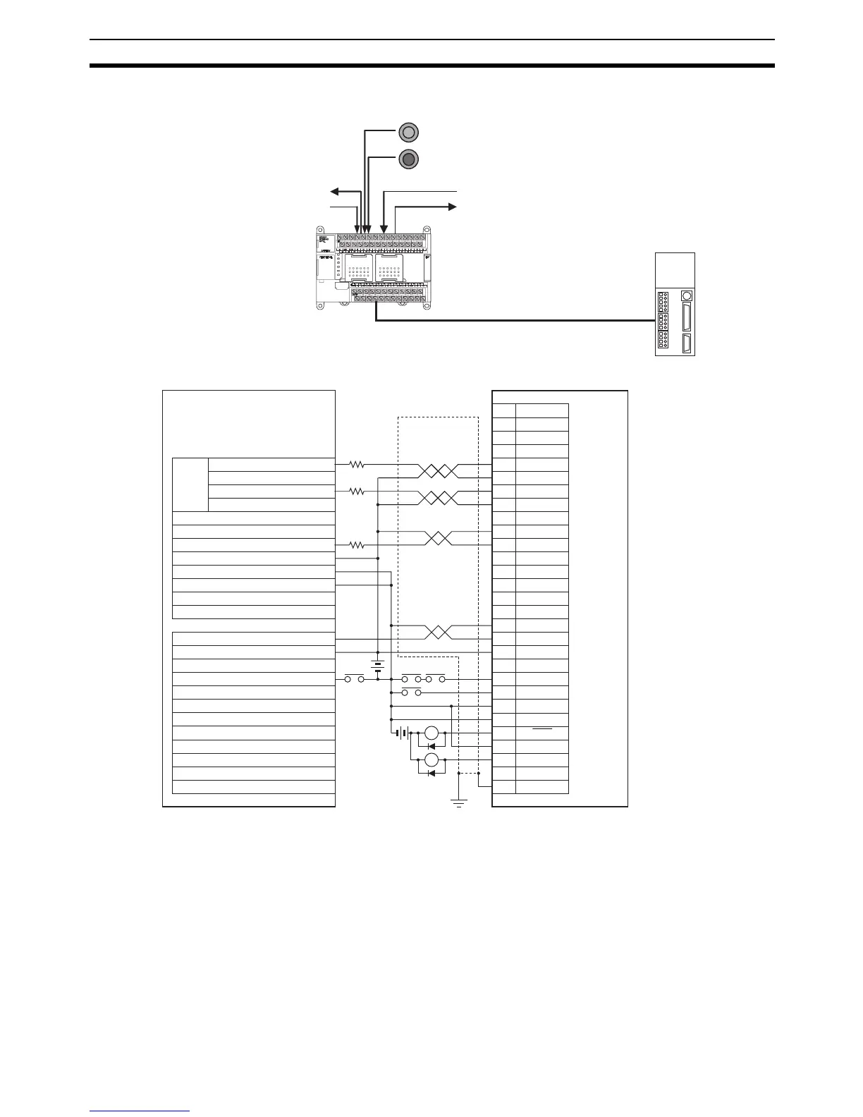
Wiring Example Using SmartStep A-series Servo Driver
Operation
1,2,3... 1. An origin search is performed using the Origin Search Switch (CIO 0.02).
2. When the origin search is finished, the PCB Storage Enabled Output
(CIO 100.03) is turned ON.
3. When a PCB has been stored, the stocker is raised (relative positioning)
using the PCB Storage Completed Input (CIO 0.03).
4. Storing PCBs is repeated until the stocker is full.
5. The number of PCBs in the stocker is counted with counter C0 by counting
the number of times the stocker is raised.
Stocker Movement Completed (CIO 0.04)
Origin Search Switch (CIO 0.02)
Emergency Stop Switch (CIO 0.05)
PCB Storage Completed (CIO 0.03)
Stocker Moving (CIO 100.02)
PCB Storage Enable (CIO 100.03)
SmartStep A-series
Servo Driver
R88A-CPU00@S and resistor
1
2
5
6
8
13
14
18
10
35
34
7
+CW
−CW
+ECRST
−ECRST
INP
33 ZCOM
32 Z
+24VIN
RUN
RESET
OGND
ALMCOM
ALM
FG
X1
XB
24 VDC
X1
Servo Driver
RUN input
24 VDC
BKIR
CW output (CIO 100.00)
CCW output (CIO 100.01)
4
3 +CCW
−CCW
24-VDC input terminal (+)
24-VDC input terminal (-)
COM (CIO 100)
COM
1.6 kΩ
1.6 kΩ
1.6 kΩ
R88A-CPU00@S
Shell
SMARTSTEP A-series Servo Driver
CP1L-M60/40/30DT-D, CP1L-20DT-D
Output Terminal Block
Pulse
output
0
Deviation counter reset output 0 (CIO 101.02)
Stocker moving (CIO 100.02)
PCB storage enable (CIO 100.03)
Input Terminal Block
Pulse 0 origin input signal (CIO 0.00)
Pulse 0 origin proximity input signal (CIO 0.01)
Origin search switch (CIO 0.02)
Emergency stop switch (CIO 0.05)
PCB storage completed (CIO 0.03)
Stocker movement completed (CIO 0.04)
Servo Driver
alarm reset input