321
Quick-response Inputs Section 5-4
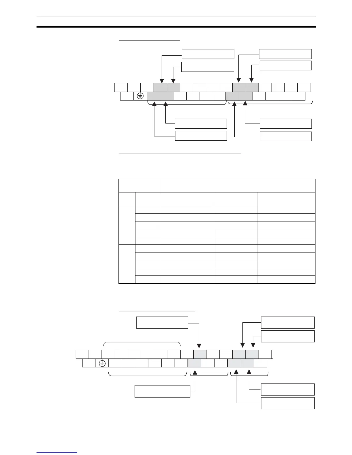
Terminal Arrangement
Setting the Input Functions in the PLC Setup
Normally, bits CIO 0.00 to CIO 0.03 and CIO 1.00 to CIO 1.03 are used as
normal inputs. When using these inputs as quick-response inputs, use the
CX-Programmer to change the input’s setting in the PLC Setup.
Y CPU Units The 6 input bits CIO 0.00 to CIO 0.01 and CIO 1.00 to CIO 1.03 can be used
as quick-response inputs.
Input Terminal Arrangement
Upper Terminal Block
(AC Power Supply Model)
L1 L2/N COM
01 05
07
09 11 01 05 07 09 11
LG
00 02 04 06 08 10 00 02 04 06 08 10
CIO 1 inputs
CIO 0 inputs
0303
Quick-response input 1
Quick-response input 3
Quick-response input 5
Quick-response input 7
Quick-response input 2
Quick-response input 0
Quick-response input 6
Quick-response input 4
Input terminal
block
Input operation setting
Word Bit Normal inputs Input interrupt Quick-response
inputs
CIO
0
00 Normal input 0 Input interrupt 0 Quick-response input 0
01 Normal input 1 Input interrupt 1 Quick-response input 1
02 Normal input 2 Input interrupt 2 Quick-response input 2
03 Normal input 3 Input interrupt 3 Quick-response input 3
04 to 11 Normal inputs 4 to 11 --- ---
CIO
1
00 Normal input 12 Input interrupt 4 Quick-response input 4
01 Normal input 13 Input interrupt 5 Quick-response input 5
02 Normal input 14 Input interrupt 6 Quick-response input 6
03 Normal input 15 Input interrupt 7 Quick-response input 7
04 to 11 Normal inputs 16 to 23 --- ---
+ − A0+ B0+ Z0+ A1+ B1+ Z1+ COM 01 05 11 01 03 05
NC
A0
−
B0
−
Z0
−
A1
−
B1
−
Z1
−
00 04 10 00 02 04
CIO 1
CIO 0
Quick-response input 1
Quick-response input 3
Quick-response input 5
Quick-response input 0
Quick-response input 4
Quick-response input 2
Dedicated high-speed counter terminals
Dedicated high-speed counter terminals
Upper Terminal Block