334
Analog I/O (XA CPU Units) Section 5-5
If the same power supply is being used by the connected devices and a dis-
connection occurs at points A or B in the above diagram, an unwanted circuit
path will occur as shown along the dotted line in the diagram. If that occurs, a
voltage of approximately 1/3 to 1/2 of the output voltage of the other con-
nected device will be generated. If that voltage is generated while the setting
is for 1 to 5 V, open-circuit detection may not be possible. Also, if a disconnec-
tion occurs at point C in the diagram, the negative (-) side will be used in for
both devices and open-circuit detection will not be possible.
This problem will not occur for current inputs even if the same power supply is
used.
Note When external power is supplied (when setting the range code), or when
there is a power interruption, pulse-form analog output of up to 1 ms may be
generated. If this causes problems with operation, take countermeasures
such as those suggested below.
• Turn ON the power supply for the CP1H CPU Unit first, and then turn ON
the power supply for the load after confirming correct operation.
• Turn OFF the power supply for the load before turning OFF the power
supply for the CP1H CPU Unit.
4. Creating a Ladder Program
I/O Allocation I/O conversion data is stored in CIO words between CIO 200 and CIO 211.
The analog voltage inputs are converted to digital values and output to CIO
words CIO 200 to CIO 203.
The digital values in CIO 210 and CIO 211 are converted (D/A conversion)
and output as analog voltage or analog current outputs.
Auxiliary Area Flags Auxiliary Area bits A434.00 to A434.03 are used as open-circuit detection
flags for the open-circuit detection function.
The Analog Initialization Completed Flag (A434.04) indicates when the built-in
analog I/O has been initialized.
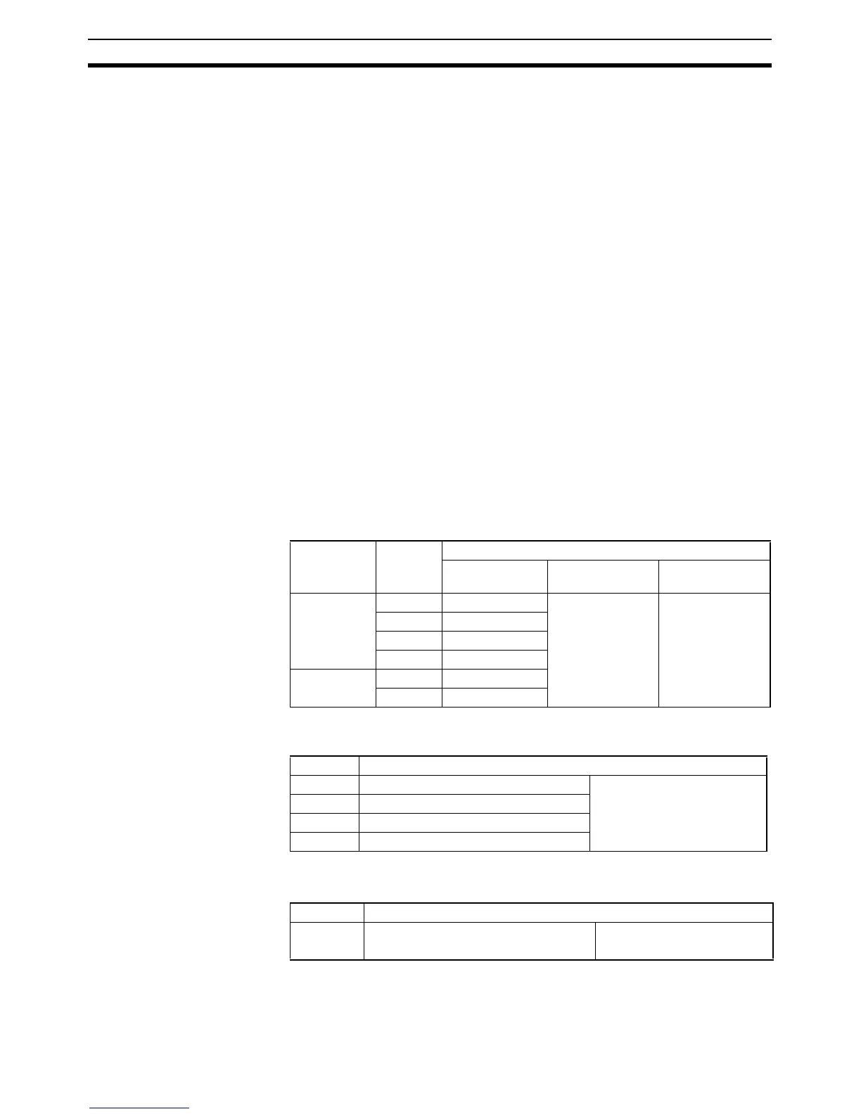
Reading Converted
Analog Input Data
The ladder program can be used to read the memory area words where the
converted values are stored. The converted digital values are output to CIO
200 to CIO 203.
Data Word Content
I/O point For 1/6,000
resolution
For 1/12,000
resolution
A/D conver-
sion data
CIO 200 Analog input 0 −10 to 10 V range:
F448 to 0BB8 hex
Other ranges:
0000 to 1770 hex
−10 to 10 V range:
E890 to 1770 hex
Other ranges:
0000 to 2EE0 hex
CIO 201 Analog input 1
CIO 202 Analog input 2
CIO 203 Analog input 3
D/A conver-
sion data
CIO 210 Analog output 0
CIO 211 Analog output 1
Bit Function
A434.00 Analog Input 0 Open-circuit Error Flag 0: No error
1: Open-circuit error detected
A434.01 Analog Input 1 Open-circuit Error Flag
A434.02 Analog Input 2 Open-circuit Error Flag
A434.03 Analog Input 3 Open-circuit Error Flag
Bit Function
A434.04 Analog Initialization Completed Flag 0: Initializing
1: Initialization completed