346
Serial Communications Section 6-1
This functionality is enabled when the serial communications mode is set to
Serial Gateway.
Contents of FINS header
• Destination network address(DNA)
a) When the routing table for network control of serial communication
channel is developed:
It is the network address that corresponds to serial communication
port according to the routing table.
b) When the routing table for networking serial communication channel is
not developed:
It is the network address when actual destination PLC is specified.
• Destination node address (DA1)
a) When the routing table for network control of serial communication
channel is developed:
00Hex (means PLC internal communication)
b) When the routing table for network control of serial communication
channel is not developed:
It is the node address when actual destination PLC is specified.
• Destination model address (DA2)
It needs to be the model address of serial communication port.
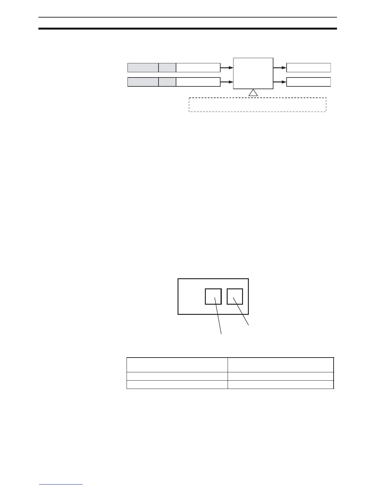
Serial communication port of CP1H
Model address of serial
communication port
Serial port 1 FDHex (decimal 253)
Serial port 2 FCHex (decimal 252)
2804
2803
The serial gateway functionality is enabled when serial port 1 or 2 is set to
the Serial Gateway Mode.
FINS message (on network or CPU bus)
FINS header CompoWay/F command
FINS header
Modbus-RTU command
Serial port 1 or
2 on CPU Unit
(Serial port 1 or 2)
CompoWay/F command
Modbus-RTU command
Serial port 2:0xFC
Serial port 1:0xFD