352
Serial Communications Section 6-1
Procedure
The Serial PLC Links operate according to the following settings in the PLC
Setup in the Polling Unit and Polled Units.
Settings at the Polling Unit
1,2,3... 1. Set the serial communications mode of serial port 1 or 2 to Serial PLC
Links (Polling Unit).
2. Set the link method to the Complete Link Method or Polling Unit Link Meth-
od.
3. Set the number of link words (up to 10 words for each Unit).
4. Set the maximum unit number in the Serial PLC Links (0 to 7).
Settings at the Polled Units
1,2,3... 1. Set the serial communications mode of serial port 1 or 2 to Serial PLC
Links (Polled Unit).
2. Set the unit number of the Serial PLC Link Polled Unit.
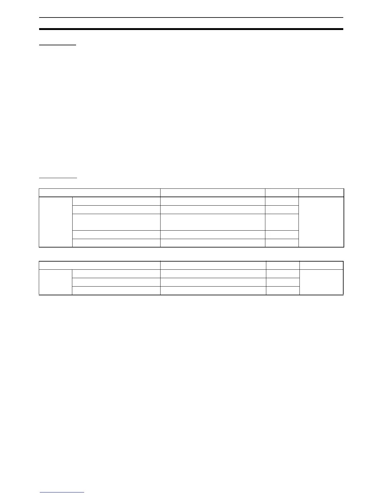
PLC Setup
Settings at the Polling Unit
Settings at the Polled Unit
Note Both serial ports cannot be used for PLC Links at the same time. If both ports
are set for PLC Links (either as polling node or polled node), a PLC Setup set-
ting error (non-fatal error) will occur and the PLC Setup Setting Error Flag
(A40210) will turn ON. If PLC Links is set for one serial port, set the other
serial port to a different mode.
Item Set value Default Refresh timing
Serial port
1 or 2
Mode: Communications mode PC Link (Master): PLC Link Polling Unit Host Link Every cycle
Baud: Baud rate 38,400 bps, 115,200 bps 9,600 bps
PC link mode: PLC Link method ALL: Complete link method
Masters: Polling Unit method
ALL
Link words: No. of link words 1 to 10 words 10 words
PC Link Unit No.: Max. unit No. 0 to 7 0 hex
Item Set value Default Refresh timing
Serial port
1 or 2
Mode: Communications mode PC Link (Slave): PLC Link Polled Unit Host Link Every cycle
Baud: Baud rate 38,400 bps, 115,200 bps 9,600 bps
Unit number 0 to 7 0