363
7-Segment LED Display Section 6-3
Memory Cassette Transfer
Progress Display
When data is transferred between the Memory Cassette and the CPU Unit, or
when a verification is started, the percentage of data remaining to be trans-
ferred or verified is displayed as a percentage (99% to 00%). It is also dis-
played for automatic transfers at startup.
Analog Adjuster Set Value
Display
When the analog adjuster is used to change a set value, that value is dis-
played in the 7-segment LED from 00 to FF hex (0 to 255). The set value is
displayed regardless of the operating mode of the CP1H CPU Unit. The dis-
play is cleared when the set value remains unchanged for at least 4 seconds.
User-defined Code
Display
The DISPLAY 7-SEGMENT LED WORD DATA (SCH(047)) and 7-SEGMENT
LED CONTROL (SCTRL(048)) instructions can be used to display any codes
or characters from the ladder program.
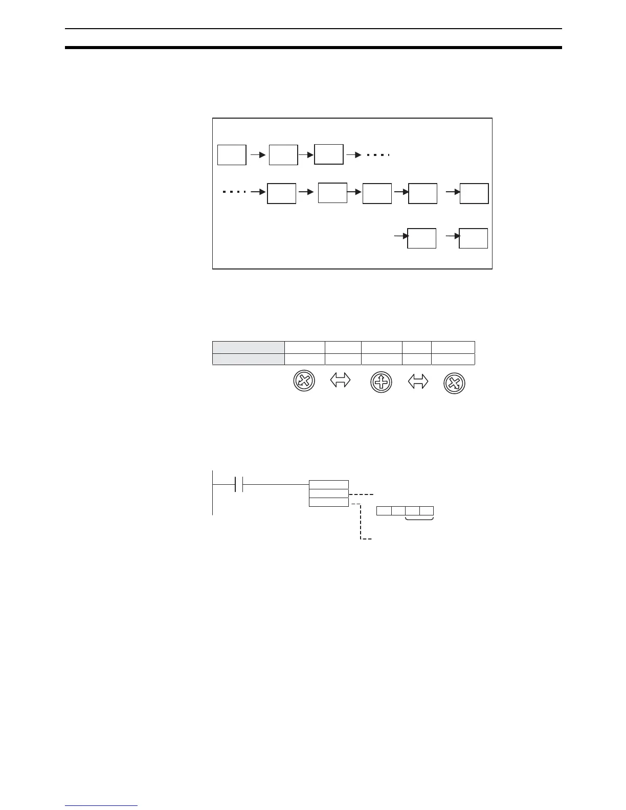
DISPLAY 7-SEGMENT LED WORD DATA: SCH (047)
When W0.01 turns ON, 2d is displayed on the 7-segment display on the CPU
Unit.
99
98
97
03
02
01
00
er.
Flashes (for 5 s)
7-segment LED display
Countdown
Flashes (for 5 s)
When a transmission error occurs
00
----
7d
----
ff
---- ----
7-segment LED display
Value in word A642
00000 (0)
007D (125)
00FF (255)
Control word (digit specification)
#0000: Displays rightmost 2 digits.
#0001: Displays leftmost 2 digits.
Display data
Data that is displayed
W0.01
D100
#0000
SCH (047)
D100
1E2D