415
Analog I/O Units Section 7-4
Handling Unit Errors
• When an error occurs in the Analog I/O Unit, analog input data will be
0000 and 0 V or 4 mA will be output as the analog output.
• CP-series Expansion Unit/Expansion I/O Unit errors are output to bits 0 to
6 of word A436. The bits are allocated from A436.00 in order starting with
the Unit nearest the CPU Unit. Use these flags in the program when it is
necessary to detect errors.
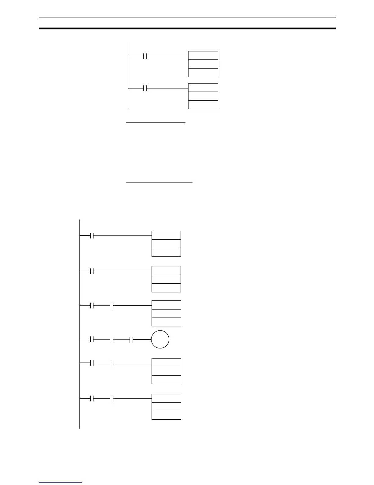
Programming Example
This programming example uses these ranges:
Analog input 0: 0 to 10 V
Analog input 1: 1 to 5 V or 4 to 20 mA
Analog output: 0 to 10 V or 4 to 20 mA
MOV(021)
2
D0
0
Always ON
P_On
TIM
T0
TIM 0 will start as soon as power turns ON.
After 0.2 to 0.3 s (200 to 300 ms), the input for
TIM 0 will turn ON, and the converted data
from analog input 0 that is stored in word 2
will be transferred to D00000.
#3
MOV(021)
#FF04
102
First Cycle ON Flag
A200.11
Always ON Flag
P_On
2
D0
T0
T0
MOV(021)
3.15
110.00
3
D1
T0
MOV(021)
D10
102
T0
MOV(021)
Execution
condition
Execution
condition
Execution
condition
Execution
condition
← Writes the range code (FF04) to the Unit.
← Reads analog input 0’s converted value.
Open-circuit alarm
← Reads analog input 1’s converted value.
← The content of D10 is written to the output
word as the analog output set value.
0
TIM
#3