455
DeviceNet I/O Link Units Section 7-7
Note (1) The 32 bits each of I/O data are not always transmitted simultaneously.
In other words, 32 bits of data transmitted from the Master CPU Unit at
the same time will not always reach the CP1H CPU Unit simultaneously,
and 32 bits of data transmitted from the CP1H CPU Unit at the same time
will not always reach the Master CPU Unit simultaneously.
When the 32 bits of input data must be read together, modify the ladder
program in the CPU Unit receiving the data. For example, read the input
data twice in succession and accept the data only when the two values
match.
(2) Unused bits in the DeviceNet I/O Link Unit’s output words can be used as
work bits if they are not used for output from the slave.
(3) Unused bits in input words cannot be used as work bits.
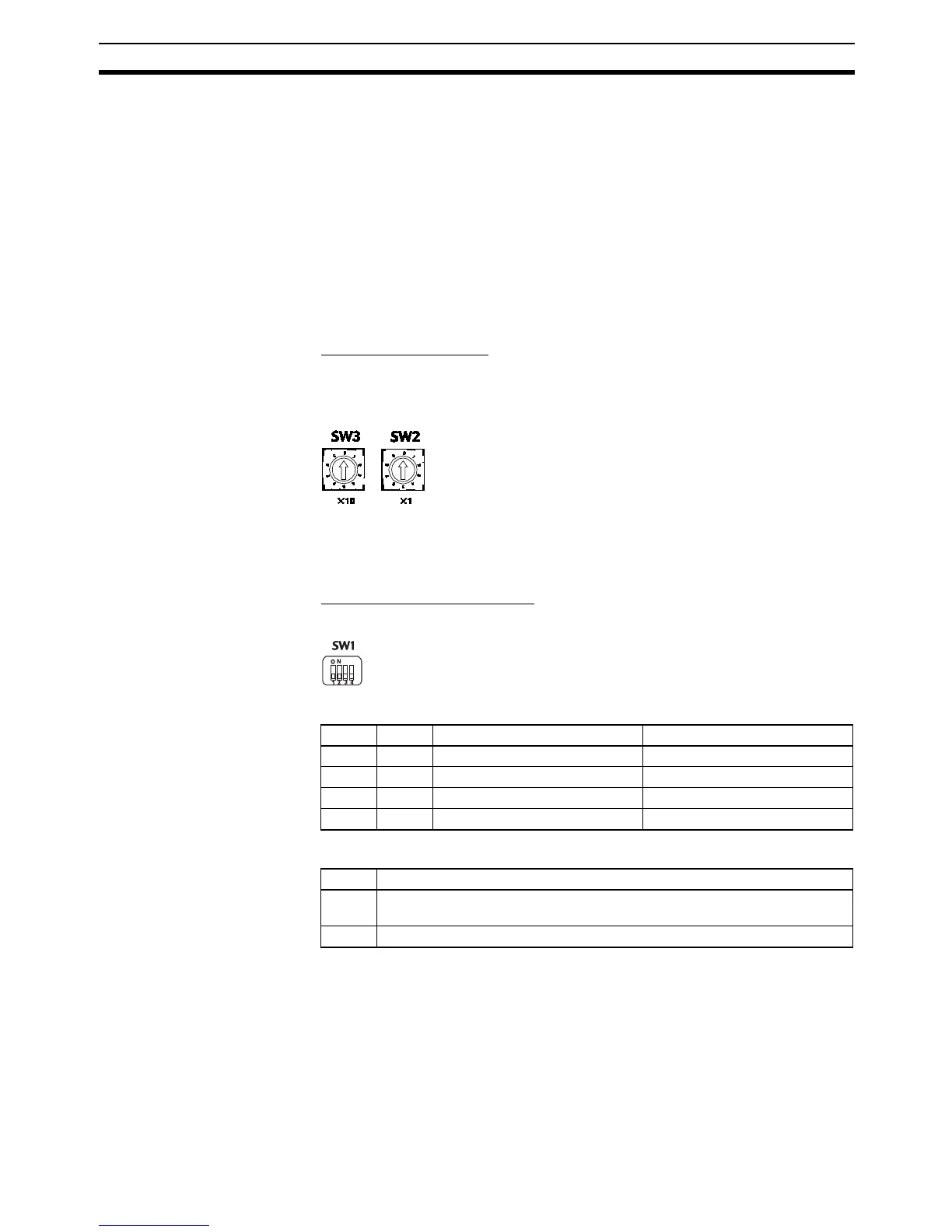
Determining the Node
Number and Making DIP
Switch Settings
Setting Node Numbers
Use rotary switches SW2 and SW3 to set DeviceNet node number. The set-
ting range is from 00 to 63, and 64 to 99 cannot be set. Rotary switch settings
go into effect when the power is turned ON.
Note The actual range of node numbers that can be set depends on the type of
PLC to which the Master Unit is mounted, and on the Master Unit setting. For
details, refer to the DeviceNet DRT1-series Slaves Operation Manual.
Setting the DIP Switch (SW1)
Used to set the DeviceNet baud rate and the output hold function.
Baud Rate
Output Hold Function
Note When using Expansion Unit/Expansion I/O Unit Error Flags (A436) in the pro-
gram, turn ON pin 4 on the DIP switch. If communications are set to be
cleared, the timing for clearing outputs and setting the Error Flags may not
agree.
Setting range: 0 to 63 (Do not set 64 to 99.)
Pin 1 Pin 2 Baud rate Max. transmission path length
OFF OFF 125 kbps 500 m
ON OFF 250 kbps 250 m
OFF ON 500 kbps 100 m
ON ON Not allowed. ---
Pin 4 DeviceNet baud rate
OFF Clears remote outputs when communications error occurs. (Outputs turned
OFF for each logic value.)
ON Holds remote outputs when communications error occurs.