45
Part Names and Functions Section 2-1
(11) Power Supply, Ground, and Input Terminal Block
(12) Option Board Slots
The following Option Boards can be mounted in either slot 1 or slot 2.
• CP1W-CIF01 RS-232C Option Board
• CP1W-CIF11/CIF12 RS-422A/485 Option Board
• CP1W-DAM01 LCD Option Board
• CP1W-CIF41 Ethernet Option Board
!Caution Always turn OFF the power supply to the PLC before mounting or removing
an Option Board.
(13) Input Indicators
The input indicators light when input terminal contacts turn ON.
(14) Expansion I/O Unit Connector
A maximum of seven CP-series Expansion I/O Units (40 I/O points, 20 I/
O points, 8 input points, 8 or output points) and Expansion Units (Analog
I/O Units, Temperature Sensor Units, CompoBus/S I/O Link Units, or
DeviceNet I/O Link Units) can be connected. (For details on using
Expansion Units and Expansion I/O Units, refer to SECTION 7 Using CP-
series Expansion Units and Expansion I/O Units.)
(15) Output Indicators
The output indicators light when output terminal contacts turn ON.
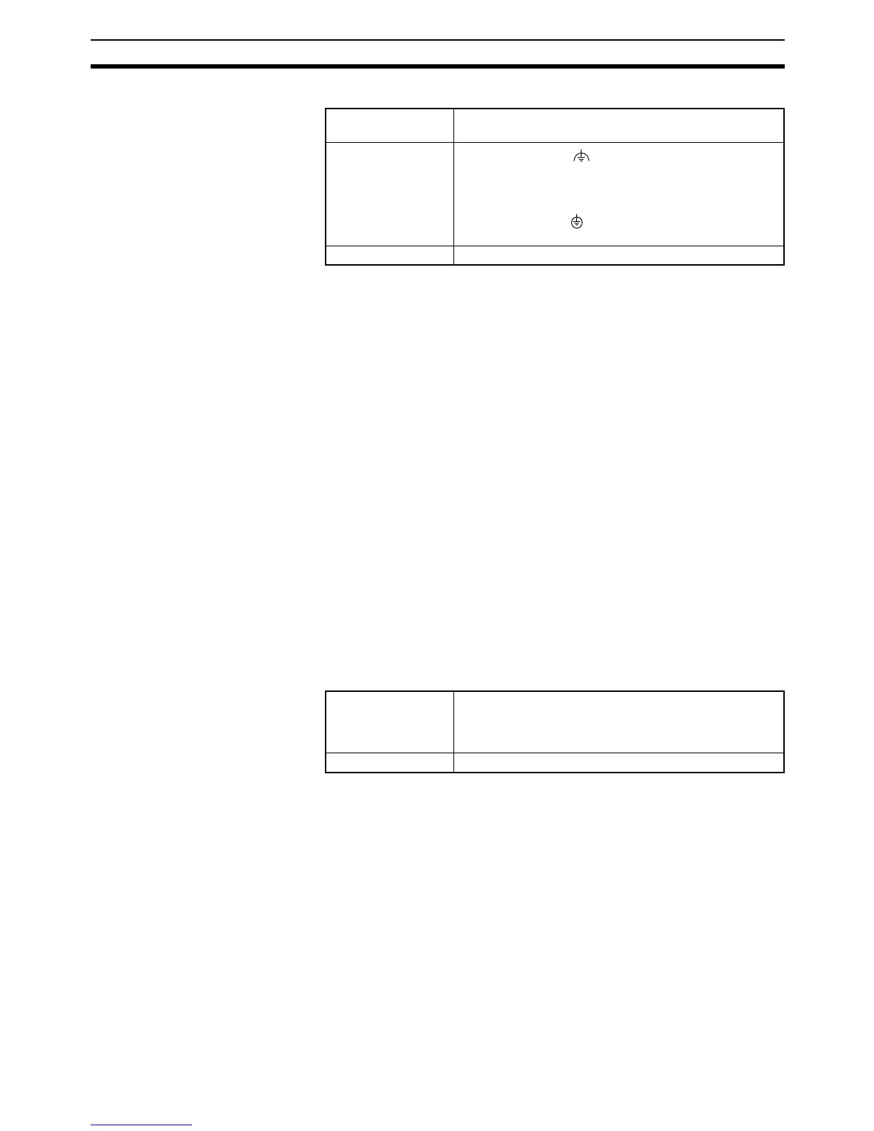
(16) External Power Supply and Output Terminal Block
Power supply ter-
minals
Used to provide a 100- to 240-VAC or 24-VDC power
supply.
Ground terminals
Functional ground ( ):
Connect this ground to strengthen noise immunity and to
prevent electric shock.
(AC power supply models only.)
Protective ground ( ):
To prevent electric shock, ground to 100 Ω or less.
Input terminals Used to connect input devices.
External power
supply terminals
XA and X CPU Units with AC power supply specifications
have external 24-VDC, 300-mA max., power supply ter-
minals. They can be used as service power supplies for
input devices.
Output terminals Used for connecting output devices.