51
Specifications Section 2-2
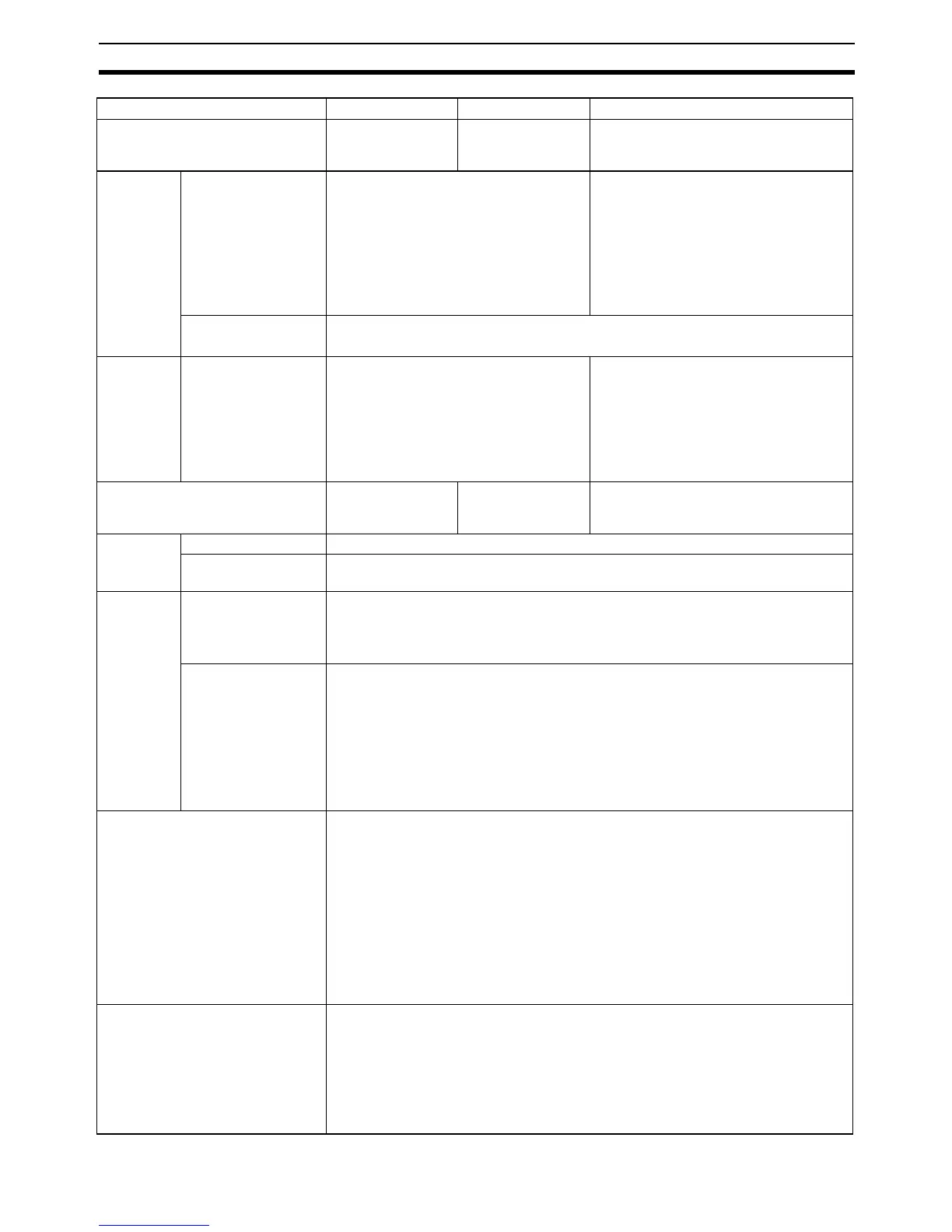
Pulse out-
puts
(Transistor
output mod-
els only)
Pulse outputs Unit version 1.0 and earlier:
2 outputs, 1 Hz to 100 kHz
2 outputs, 1 Hz to 30 kHz
Unit version 1.1 and later:
4 outputs, 1 Hz to 100 kHz
(CCW/CW or pulse plus direction)
Trapezoidal or S-curve acceleration and
deceleration (Duty ratio: 50% fixed)
2 outputs, 1 Hz to 100 kHz
Trapezoidal or S-curve acceleration and
deceleration (Duty ratio: 50% fixed)
PWM outputs 2 outputs, 0.1 to 6,553.5 Hz
Duty ratio: 0.0% to 100.0% variable (Unit: 0.1%) (Accuracy: ±5% at 1 kHz)
Special
pulse out-
put termi-
nals
Pulse outputs None 2 outputs, 1 Hz to 1 M Hz (CCW/CW or
pulse plus direction, line-driver outputs)
Trapezoidal or S-curve acceleration and
deceleration (Duty ratio: 50% fixed)
Note Special pulse output terminals are
line-driver outputs, so they cannot
be used as normal outputs.
Built-in analog I/O terminals None 4 analog inputs and
2 analog outputs
(See note 1.)
None
Analog set-
tings
Analog adjuster 1 (Setting range: 0 to 255)
External analog set-
ting input
1 input (Resolution: 1/256, Input range: 0 to 10 V)
Serial port Peripheral USB port Supported. (1-port USB connector, type B): Special for a Peripheral Device such as
the CX-Programmer. (Set the network classification to USB in the Peripheral
Device's PLC model setting.)
• Serial communications standard: USB 1.1
RS-232C port, RS-
422A/485 port
Ports not provided as standard equipment. (2 ports max.)
The following Option Boards can be mounted:
• CP1W-CIF01: One RS-232C port
• CP1W-CIF11/CIF12: One RS-422A/485 port
Applicable communications modes (same for all of the above ports): Host Link, NT
Link (1: N mode), No-protocol, Serial PLC Link Slave, Serial PLC Link Master, Serial
Gateway (conversion to CompoWay/F, conversion to Modbus-RTU), peripheral bus
(See note 2.)
7-segment display 2-digit 7-segment LED display (red)
• At startup: The Unit version is displayed.
• When a CPU Unit error occurs: The error code and error details are displayed in
order (fatal error, non-fatal error).
• When a special instruction is executed: The DISPLAY 7-SEGMENT LED WORD
DATA (SCH) instruction displays the upper or lower byte of specified word data,
and the 7-SEGMENT LED CONTROL (SCTRL) instruction controls the ON/OFF
status of each segment.
• While data is being transferred between a Memory Cassette and the CPU, the
remaining amount to be transferred is displayed as a percentage.
• When the analog adjuster is adjusted, the value is displayed from 00 to FF.
Number of tasks 288 (32 cycle execution tasks and 256 interrupt tasks)
Scheduled interrupt tasks: 1 (interrupt task 2, fixed)
Input interrupt tasks: 8 (interrupt tasks 140 to 147, fixed)
Note Y CPU Units have 6 input interrupt tasks. (Interrupt tasks 140 to 145 can be
used.)
(High-speed counter interrupts and interrupt tasks specified by external inter-
rupts can also be executed.)
Type X CPU Units XA CPU Units Y CPU Units
Model CP1H-X40DR-A
CP1H-X40DT-D
CP1H-X40DT1-D
CP1H-XA40DR-A
CP1H-XA40DT-D
CP1H-XA40DT1-D
CP1H-Y20DT-D