57
Specifications Section 2-2
Interrupt Inputs and
Quick-response Inputs
Input bits CIO 0.00 to CIO 0.03 and CIO 1.00 to CIO 1.03 can be used not
only as normal inputs but also as interrupt or quick-response inputs depend-
ing on the settings in the PLC Setup.
The ON/OFF response time is 8 ms for normal inputs, but it can be changed
in the PLC Setup to 0, 0.5, 1, 2, 4, 8, 16, or 32 ms.
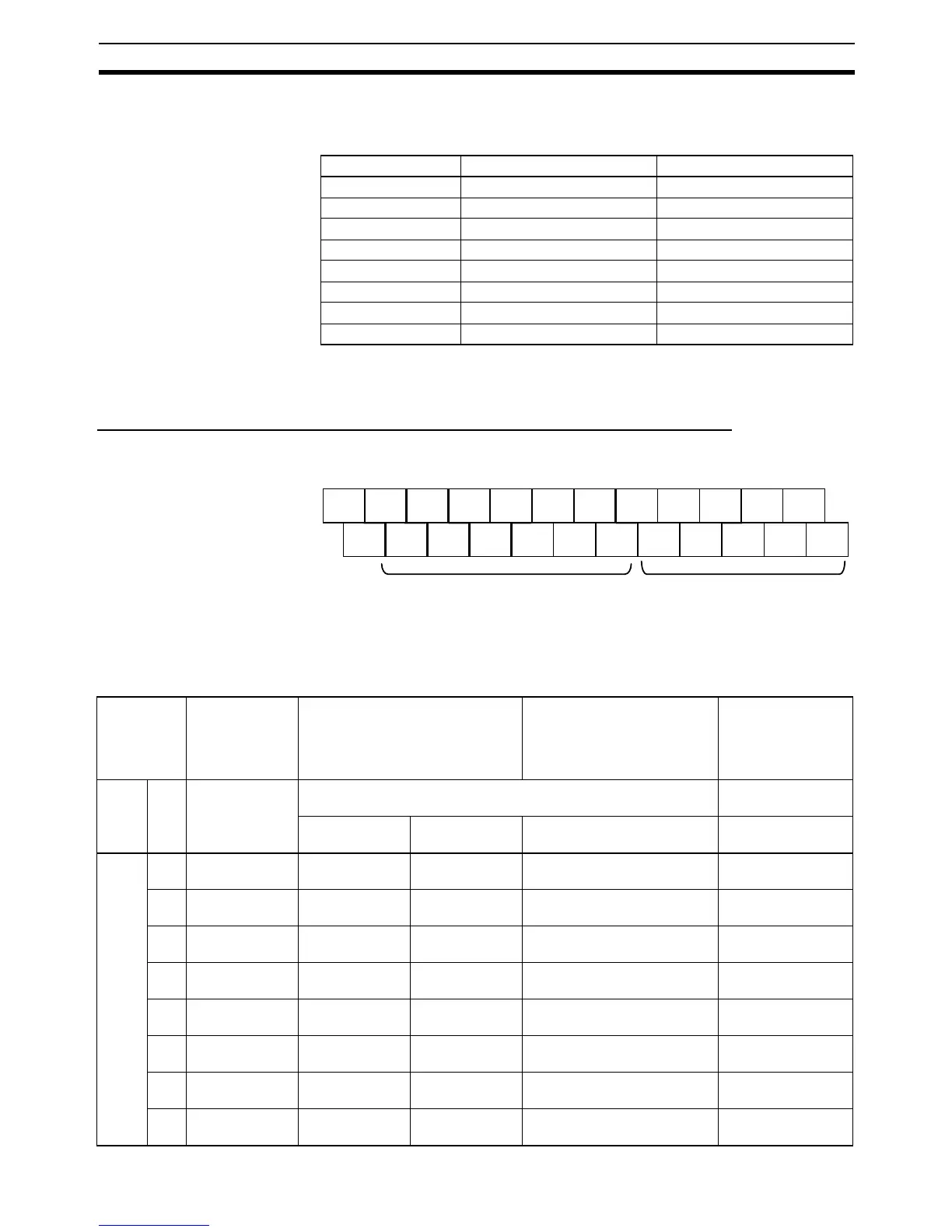
Relationship between Built-in Outputs and Terminal Block Arrangement
Terminal Block Arrangement
Setting Functions Using
Instructions and PLC
Setup
Pulses can be output from the normal output terminals in the built-in outputs
by executing pulse output instructions. To use the ORIGIN SEARCH (ORG)
instruction, all of the pulse output settings in the PLC Setup must be set.
Input bit Interrupt inputs Quick-response inputs
CIO 0.00 Interrupt input 0 Quick-response input 0
CIO 0.01 Interrupt input 1 Quick-response input 1
CIO 0.02 Interrupt input 2 Quick-response input 2
CIO 0.03 Interrupt input 3 Quick-response input 3
CIO 1.00 Interrupt input 4 Quick-response input 4
CIO 1.01 Interrupt input 5 Quick-response input 5
CIO 1.02 Interrupt input 6 Quick-response input 6
CIO 1.03 Interrupt input 7 Quick-response input 7
NC 00 01 02 03 04 06 00 01 03 04 06
NC COM COM COM COM 05 07 COM 02 COM 05 07
Lower Terminal Block (Example: Transistor Outputs)
CIO 100 CIO 101
Normal output terminals
Output
terminal
block
When the
instructions to
the right are
not executed
When a pulse output instruction
(SPED, ACC, PLS2, or ORG) is
executed
When the origin search
function is set to be used in
the PLC Setup, and an
origin search is executed by
the ORG instruction
When the PWM
instruction is
executed
Word Bit Normal
outputs
Fixed duty ratio pulse output Variable duty ratio
pulse output
CW/CCW Pulse plus
direction
+ When the origin search
function is used
PWM output
CIO
100
00 Normal output 0 Pulse output 0
(CW)
Pulse output 0
(pulse)
--- ---
01 Normal output 1 Pulse output 0
(CCW)
Pulse output 1
(pulse)
--- ---
02 Normal output 2 Pulse output 1
(CW)
Pulse output 0
(direction)
--- ---
03 Normal output 3 Pulse output 1
(CCW)
Pulse output 1
(direction)
--- ---
04 Normal output 4 Pulse output 2
(CW)
Pulse output 2
(pulse)
--- ---
05 Normal output 5 Pulse output 2
(CCW)
Pulse output 2
(direction)
--- ---
06 Normal output 6 Pulse output 3
(CW)
Pulse output 3
(pulse)
--- ---
07 Normal output 7 Pulse output 3
(CCW)
Pulse output 3
(direction)
--- ---